Parts List
- .06 Ohm Metal Cased Resistor (25W or greater)
- LM393N Voltage Comparator
- 2x 2N3904 NPN Transitors
- 390 Ohm 1 Watt Resistor
- 100 Ohm ¼ watt 5% Resistors
- 1.0 K Ohm ¼ watt 5% Resistors
- 1.5 K Ohm ¼ watt 5% Resistors
- 5.6 K Ohm ¼ watt 5% Resistors
- Common Red LED
- Piezo Audio Buzzer (see below)
- (Optional) 2x .01 µF Tantalum capacitors
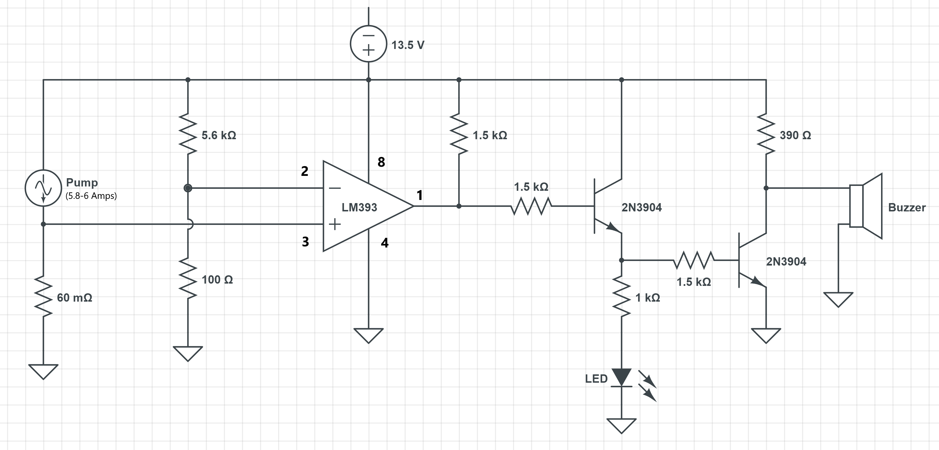
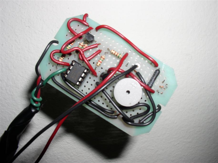
This circuit operates using an LM393 Voltage Comparator to determine whether the current through the electric water pump has fallen below a specified threshold. The output of this comparitor (pin 1) is high whenever the + input voltage is greater than the - input voltage, and the output of the comparitor is low when the - input is greater than the + input to the device. The normal operation (No Pump Failure) of the circuit is designed so the comparitor output is high and both transistors are biased on. When the transistors are turned on the LED has current flowing through it and illuminates. The buzzer is seeing less than .3 volts with the transistors on and will not turn on.
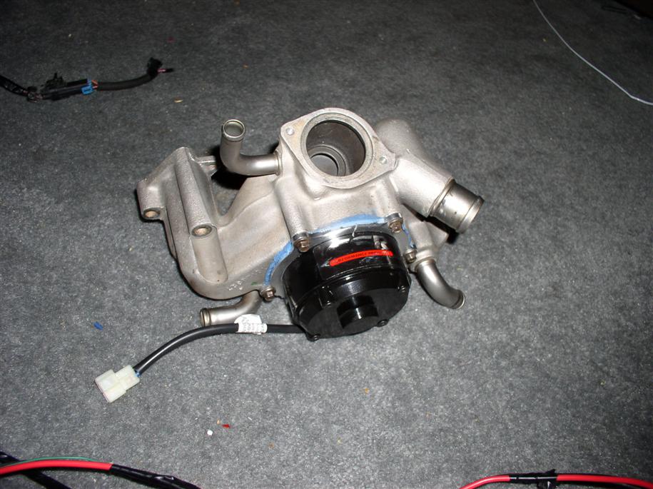
In this circuit it is important to understand the function of the 60 milliohm (.06 ohm) resistor in the circuit. This resistor as a current sensor and can sometimes be referred to as a shunt resistor in this configuration. It is very important that the resistor is installed correctly to function properly. The resistor should be installed in the pump ground wire within a few inches of the actual ground termination lug. The sense wire to pin 3 of the comparitor needs to be installed on the pump side solder terminal of the shunt resistor so that it senses only the voltage dropped across the resistor.
When the normal operating current (5.8-6 Amps) is flowing through the shunt resistor it drops between 346-360 millivolts. This sense voltage is applied to pin 3 of the LM393. Pin 2 of the LM 393 is fixed by a voltage divider to 240 millivolts. The fixed voltage at pin 2 is the threshold for the alarm to trigger. When the sense voltage falls below 240 millivolts the comparitor output (pin 1) goes low. This action extinguishes the LED and the buzzer will sound. The comparitor threshold at pin 2 (240 millivolts) is set to trigger the alarm when pump current falls below 4 amps.
When Substituting in a 50 Milliohm Shunt Resistor
I have also substituted a 50 milliohm shunt resistor into the sensing circuit when I have not been able to find the 25 watt 60 milliohm resistors. When using a 50 milliohm shunt resistor the 5.6K ohm resistor in the voltage divider circuit should be replaced by a 6.8K ohm resistor to maintain the alarm threshold at 4 amps through the pump.
Parts List Notes
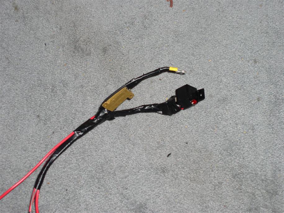
The .06 Ohm (60-milliohm) resistor in the coolant pump return will dissipate over 2 watts. A minimum power rating for this resistor should be 5 watts. But this may not be suitable for your installation as the only 5-watt resistors I found had axial leads, which seemed too small. I used a 25-watt metal case resistor that had generous soldering lugs for the 12 gage pump wires. I have found that the best resistors for this application are the metal cased wire wound power resistors.
The 390 Ohm resistor will dissipate close to ½ watt. The minimum power rating for this resistor should be 1 watt.
The remaining resistors in this circuit are ¼ watt 5% resistors.
The LED is speced to be a common red LED that drops 1.6 VDC with a nominal current of between 12-20 mA.
The Buzzer in this circuit is a piezo audio buzzer with the following specifications:
- Operating Voltage 3 - 16 VDC
- Rated Voltage 12 VDC
- Current Consumption 5.8 mA
- Resonant Frequency 4000 Hz
- Sound Pressure Level @ 10 cm Typical 86 dBA
It can be purchased online from Jameco Electronics as P/N 196357
Note: In later versions of this circuit I installed a couple of .01 µF Tantalum caps. One connected between the VCC to Ground, and the second between Pin 3 of the comparitor to ground. This should eliminate any noise from coupling into the circuit from the engine.
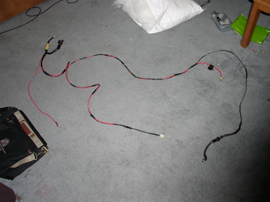
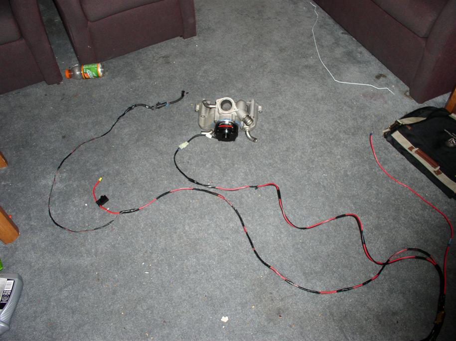
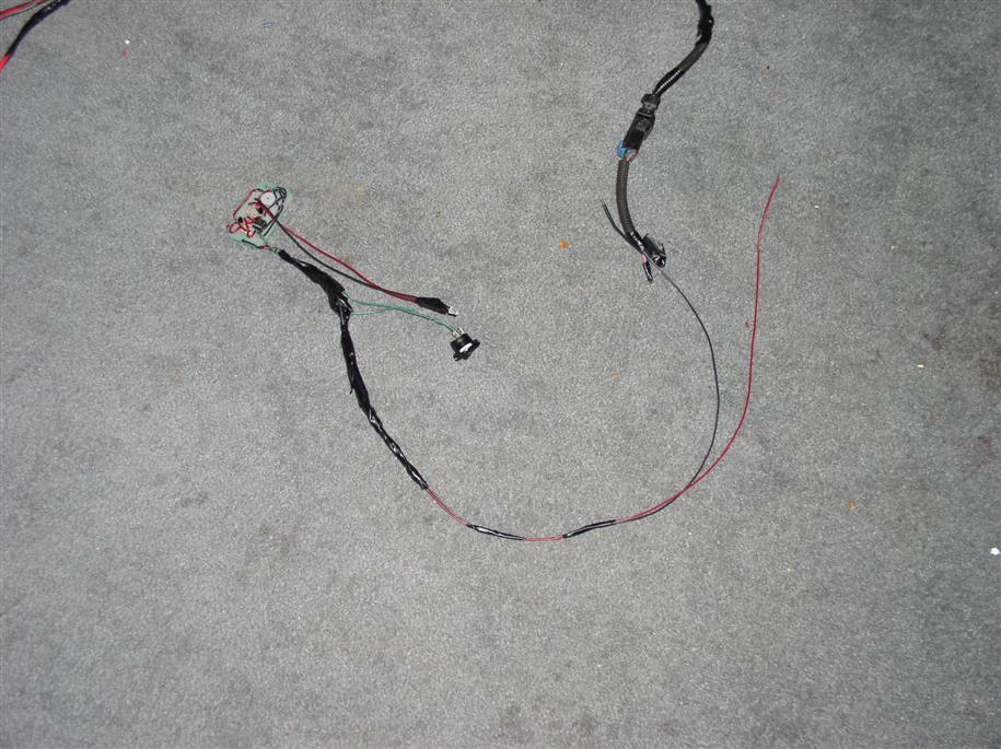
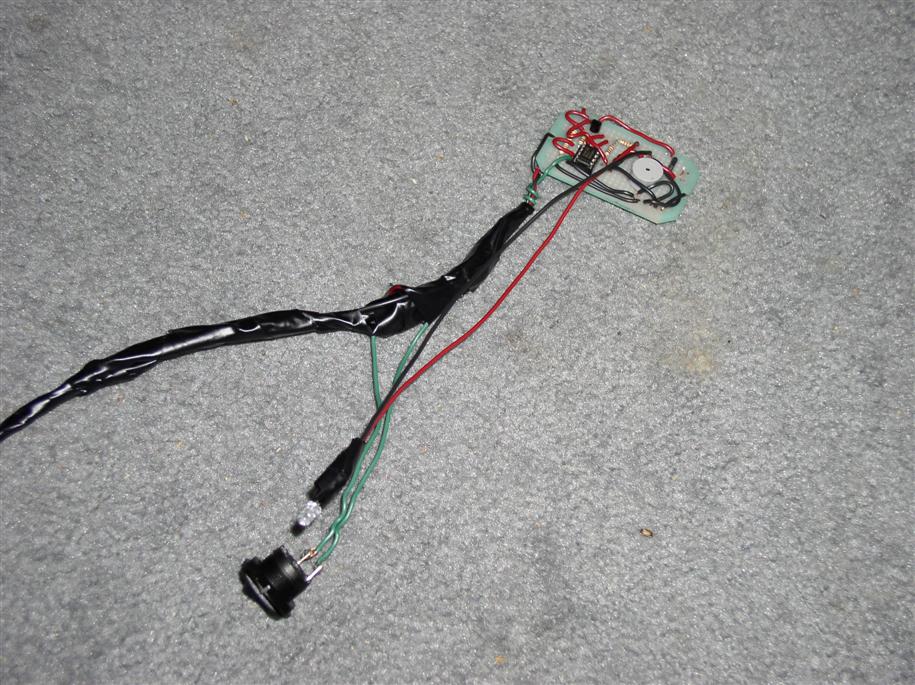
Building a wiring harness
I built the circuit above and combined it with the basic electric water pump wiring (basically, a relay from ignition to a relay giving +12V to the pump).