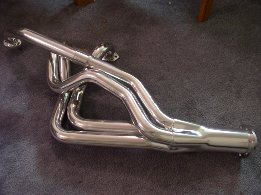
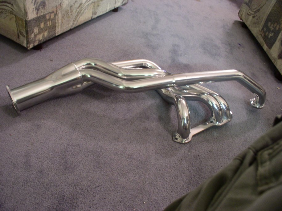
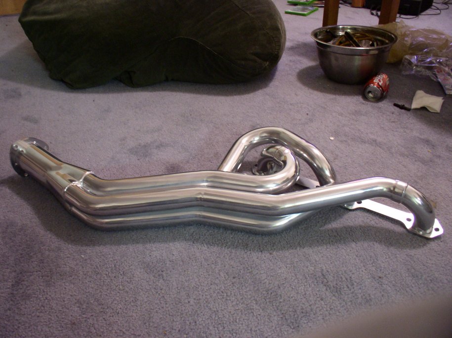
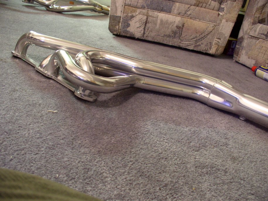
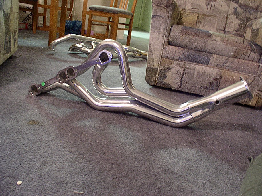
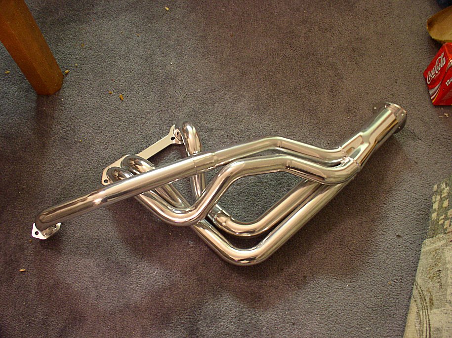
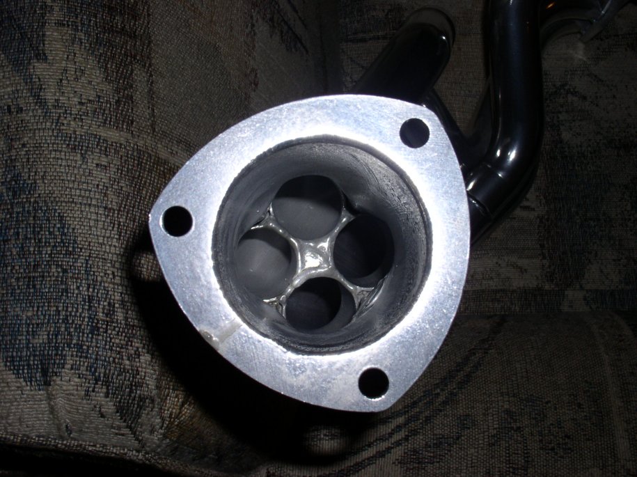
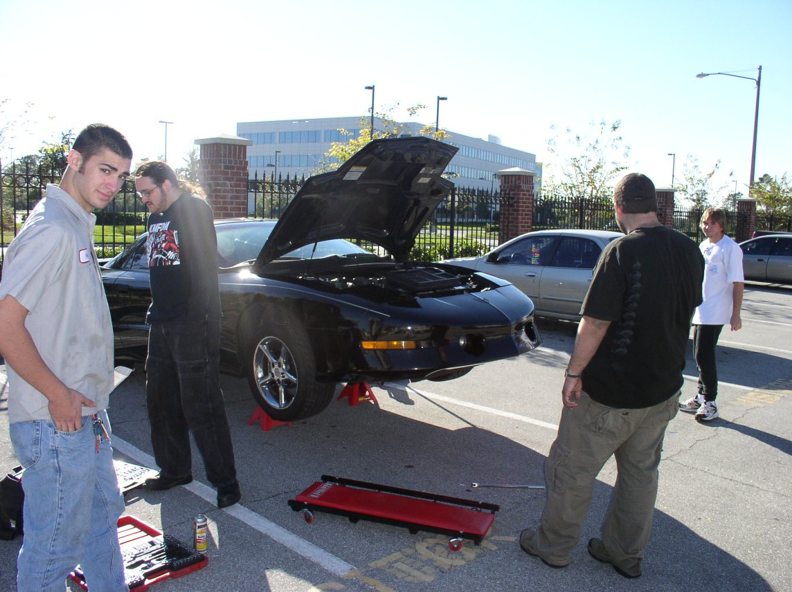
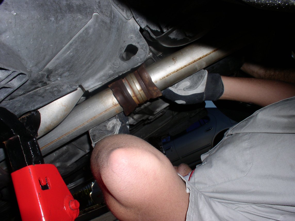
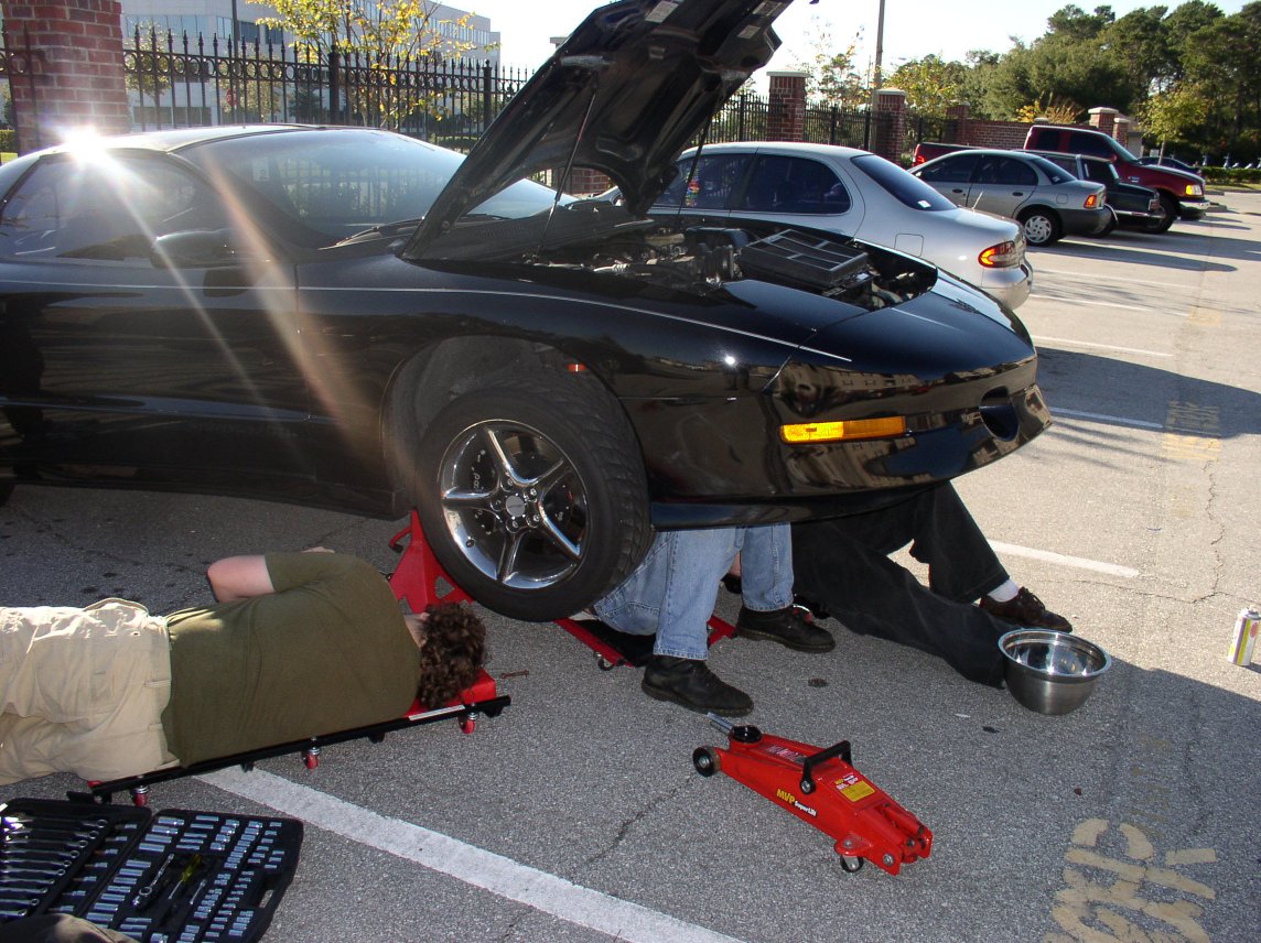
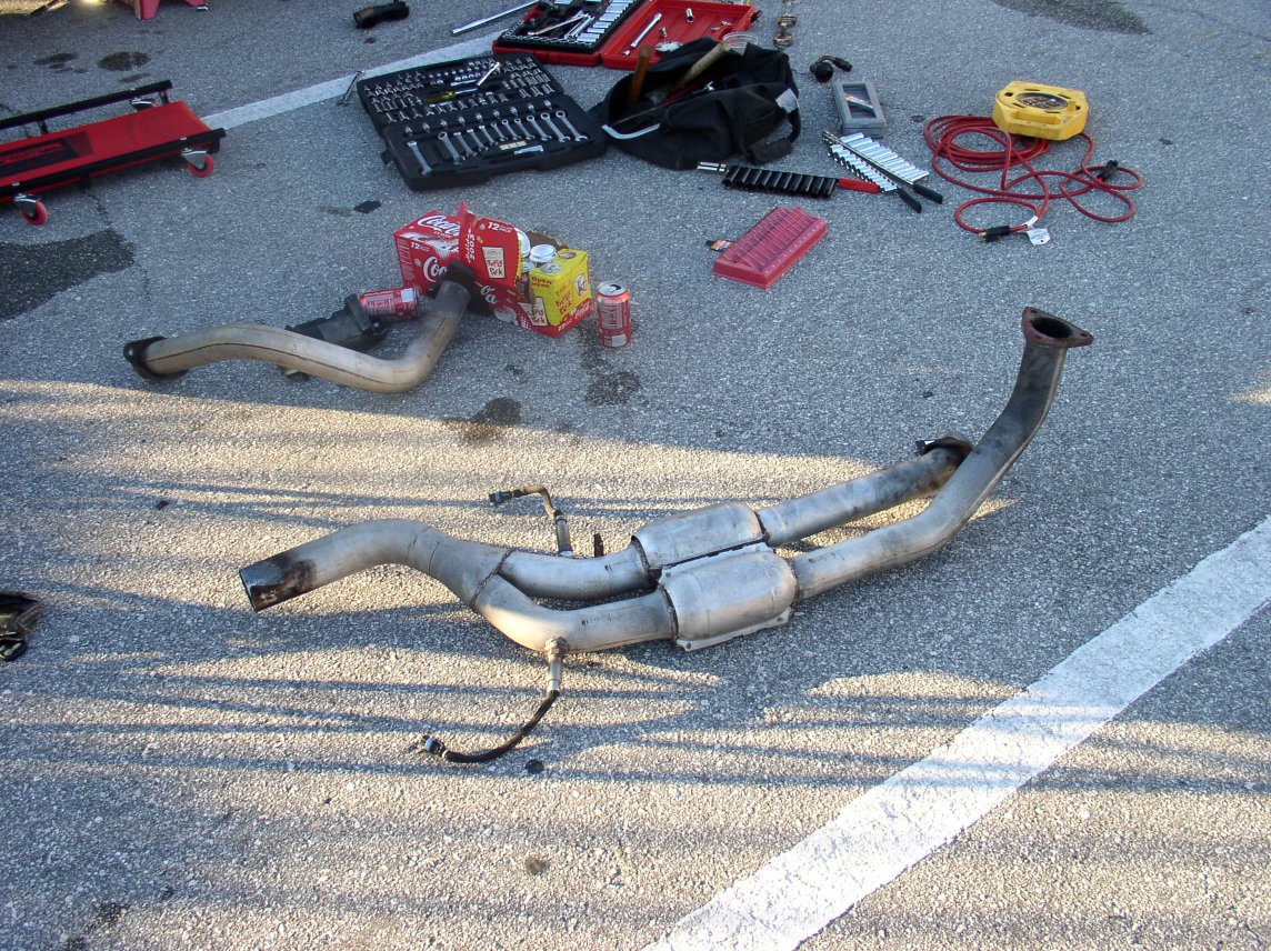
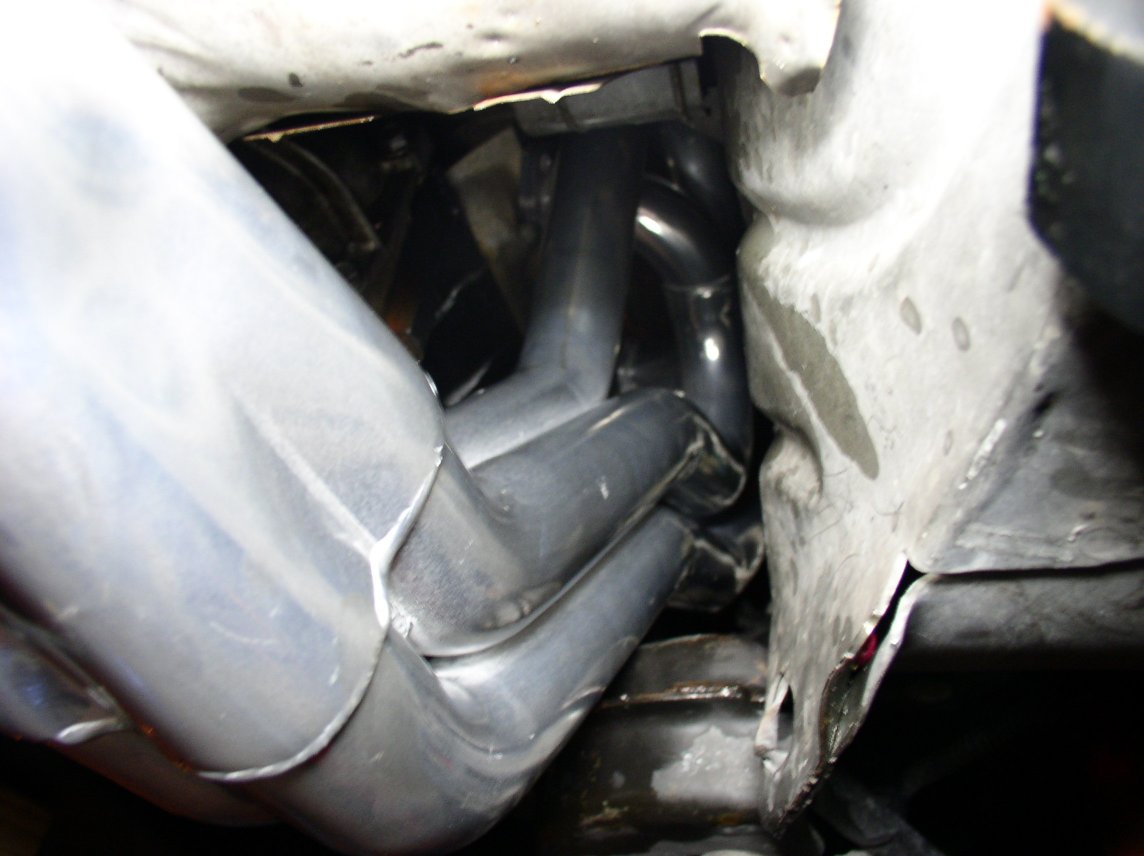
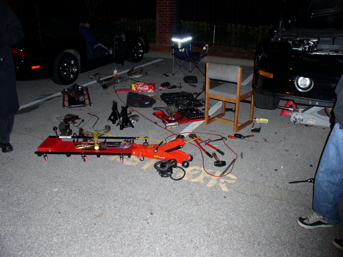
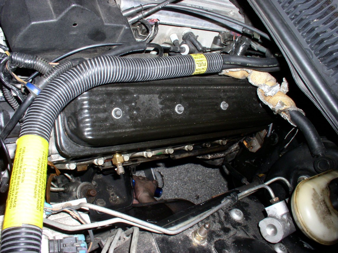
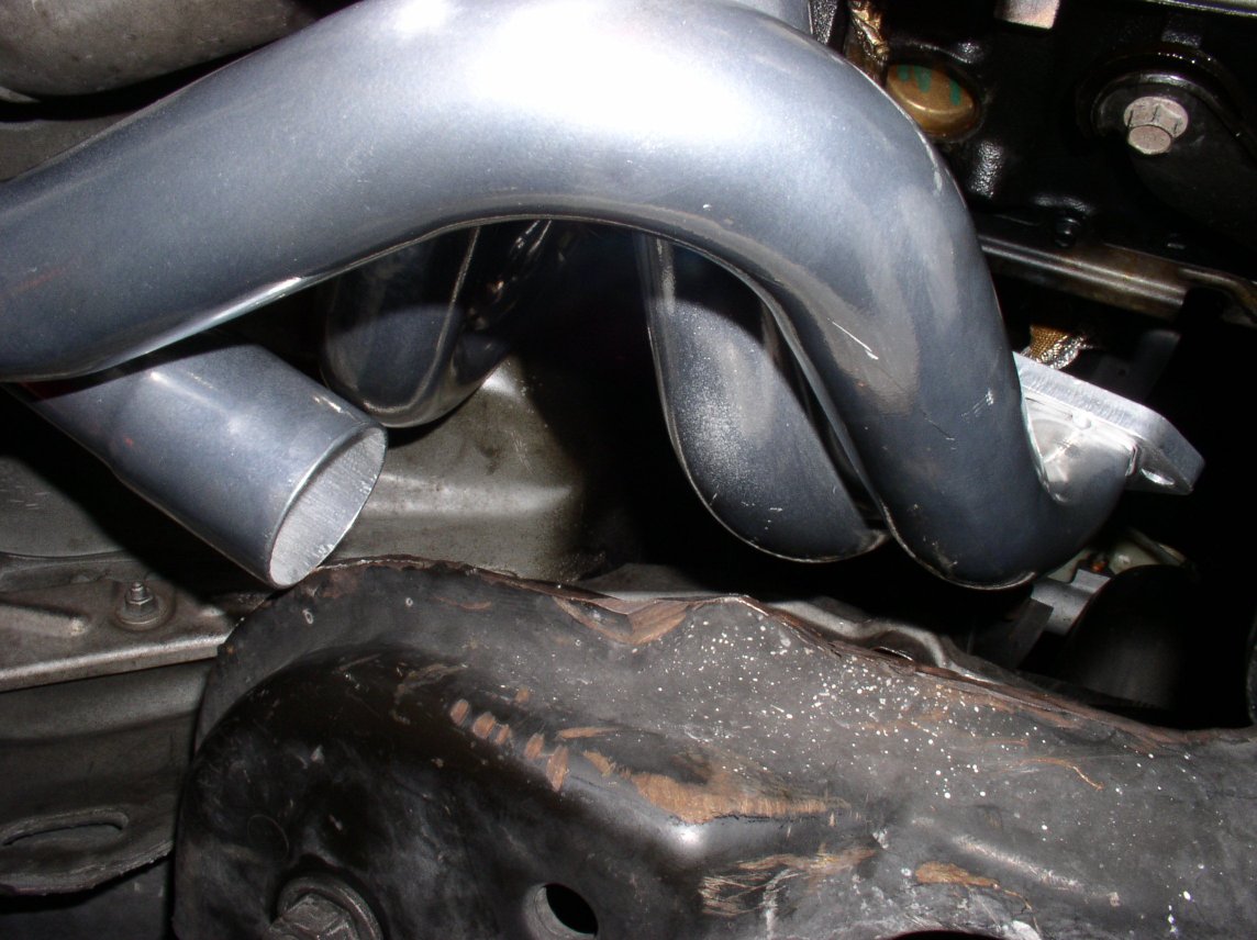
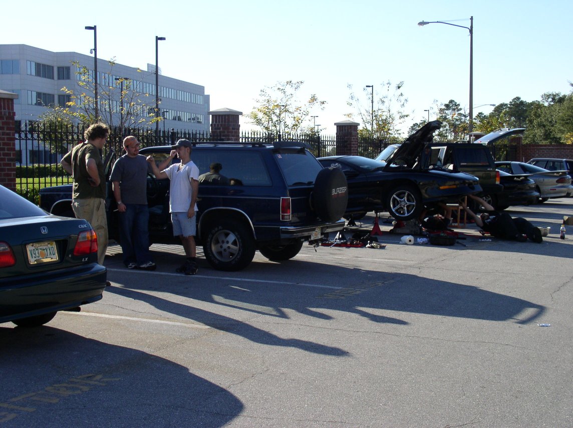
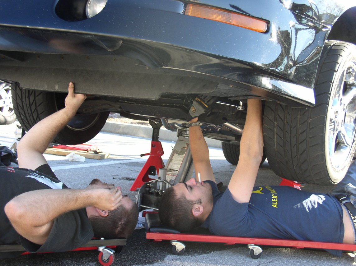
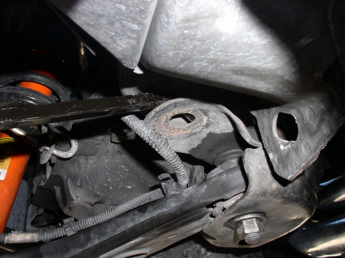
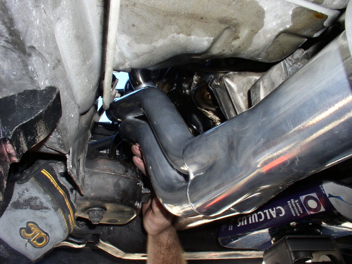
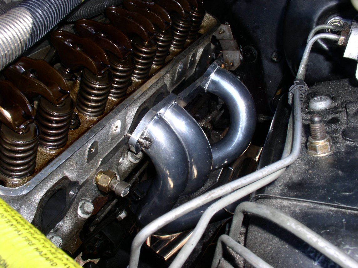
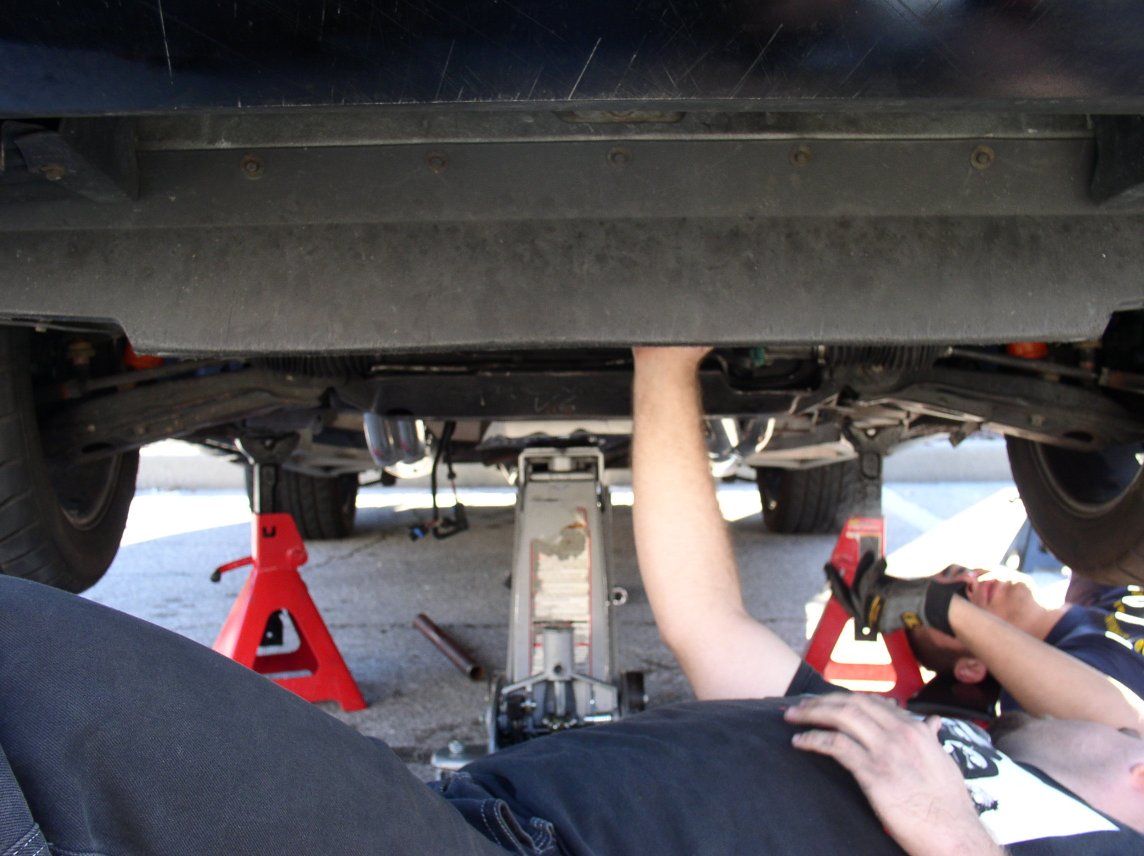
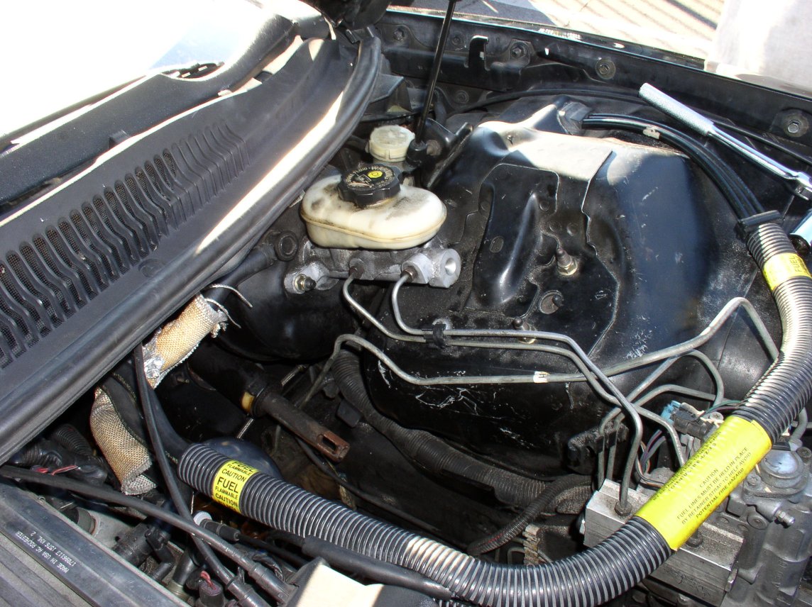
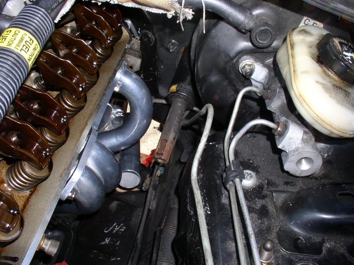
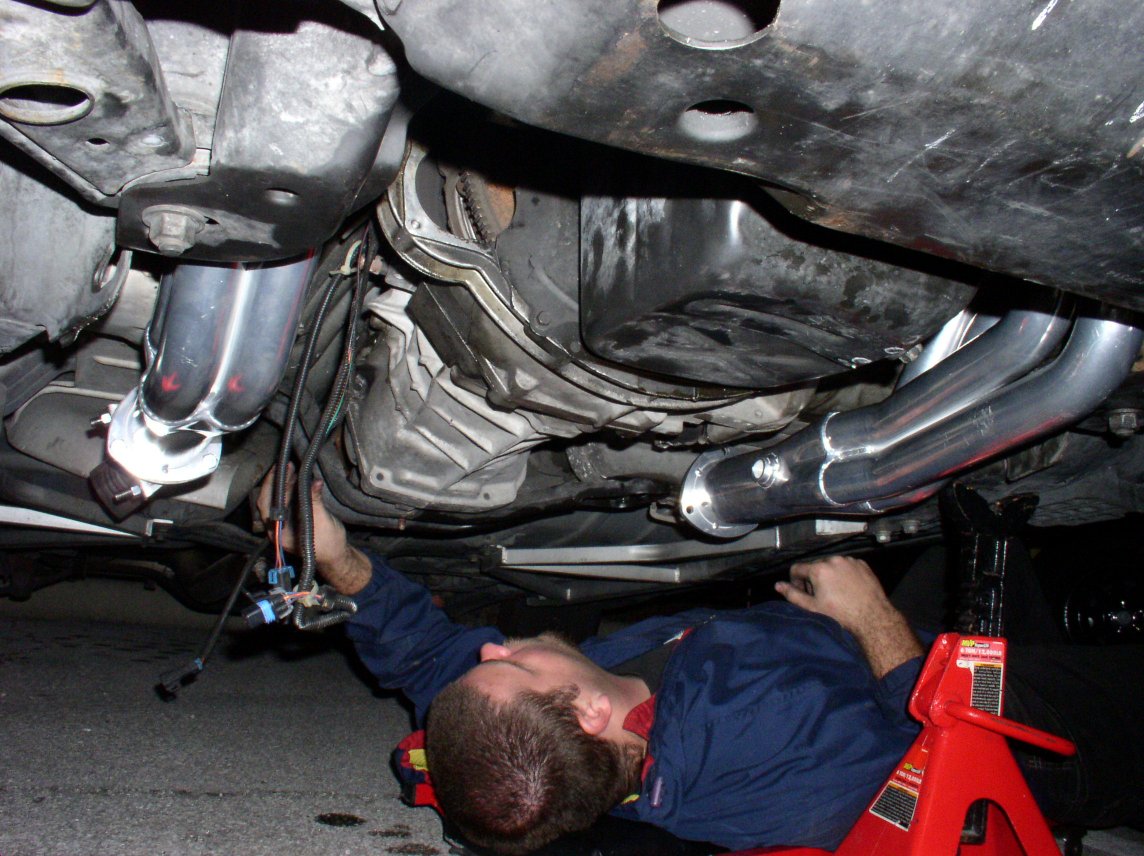
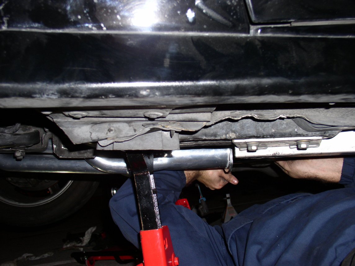
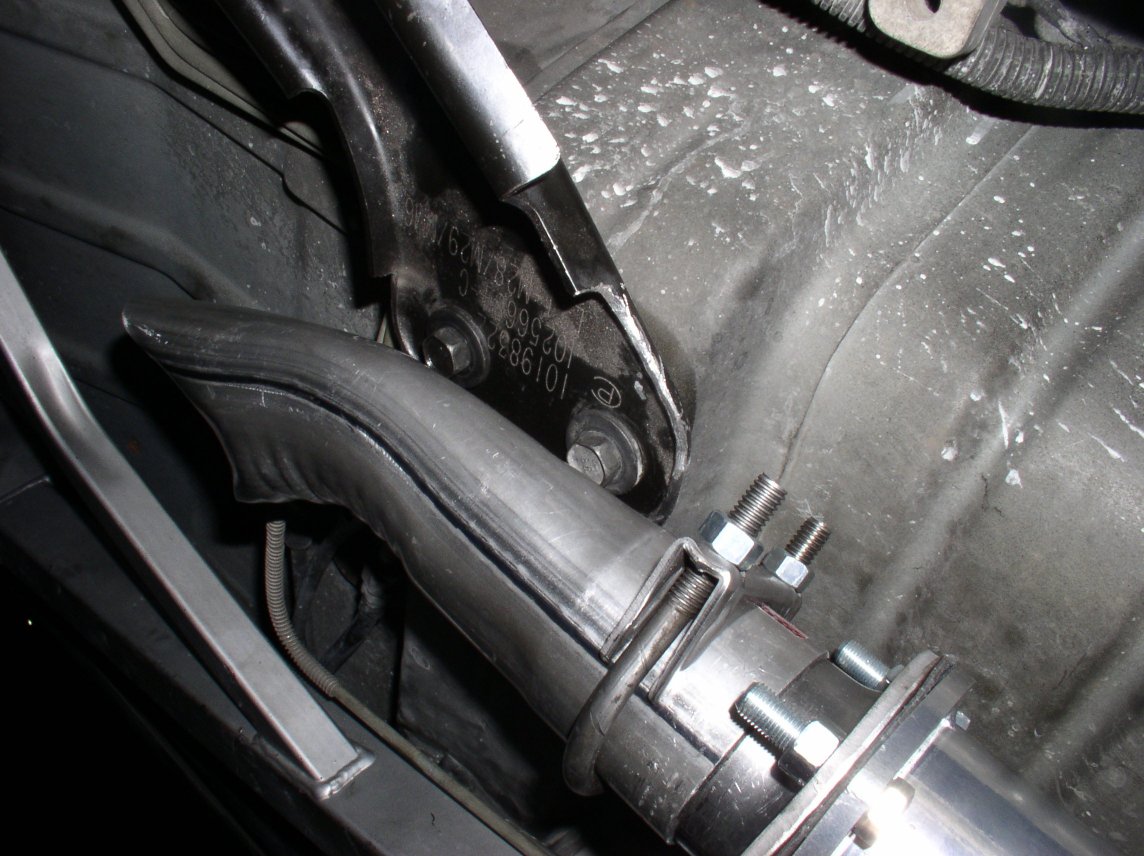
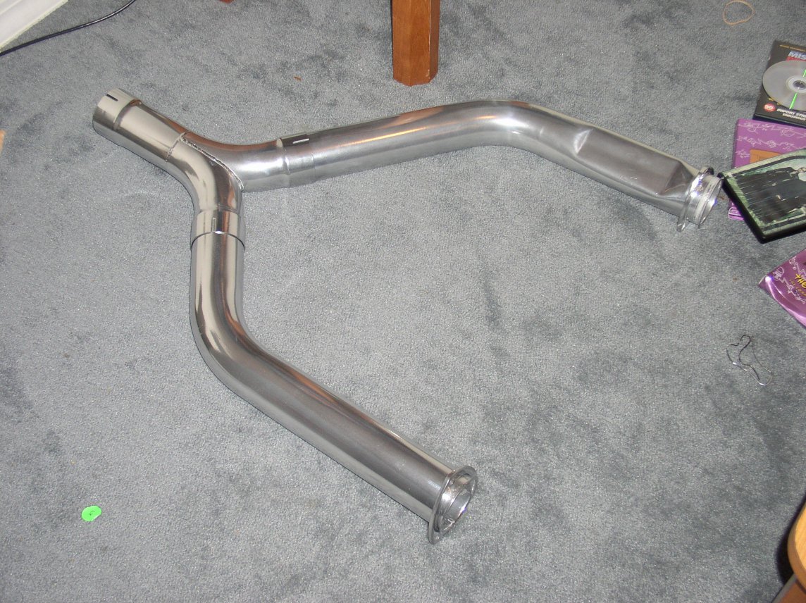
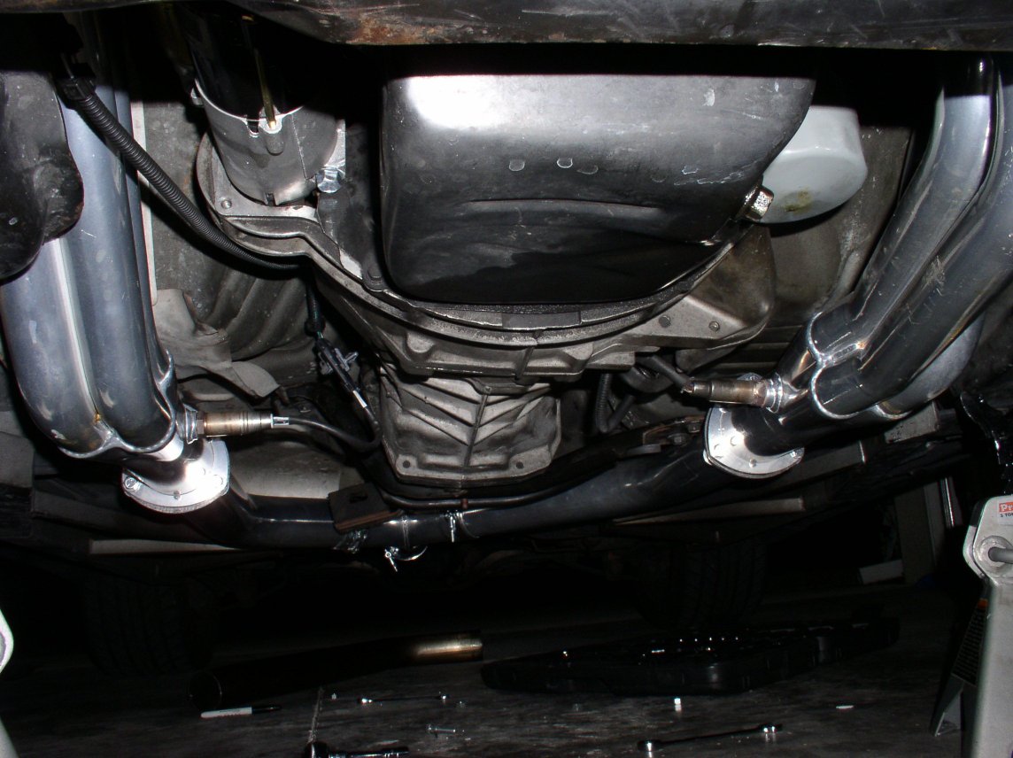
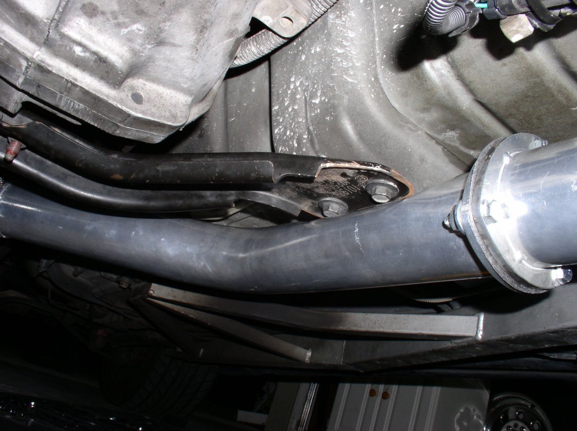
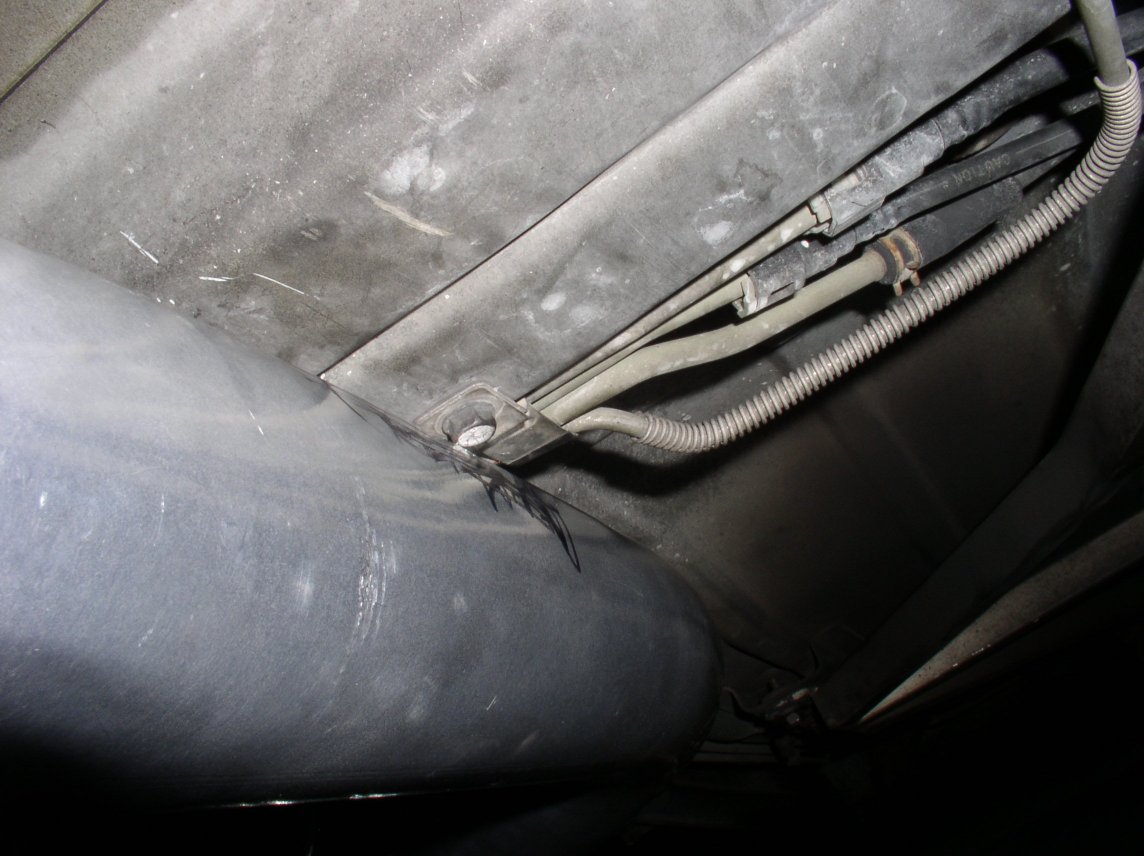
Jet Hot Longtube Headers and Y-Pipe Install

The Parts

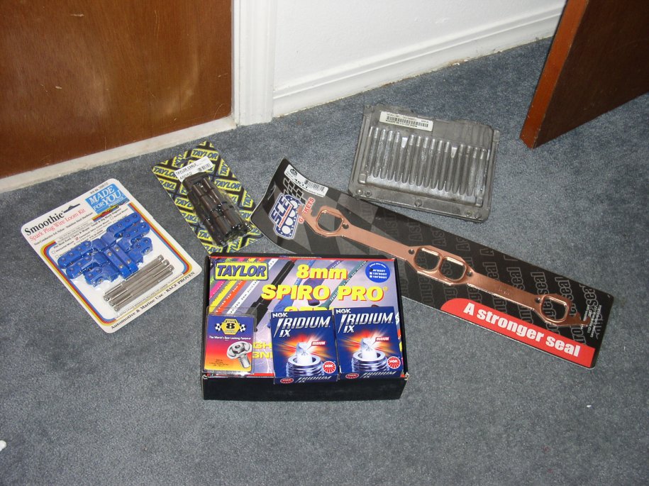
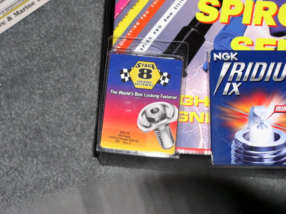
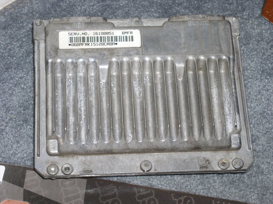
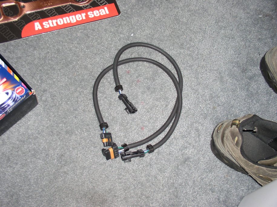
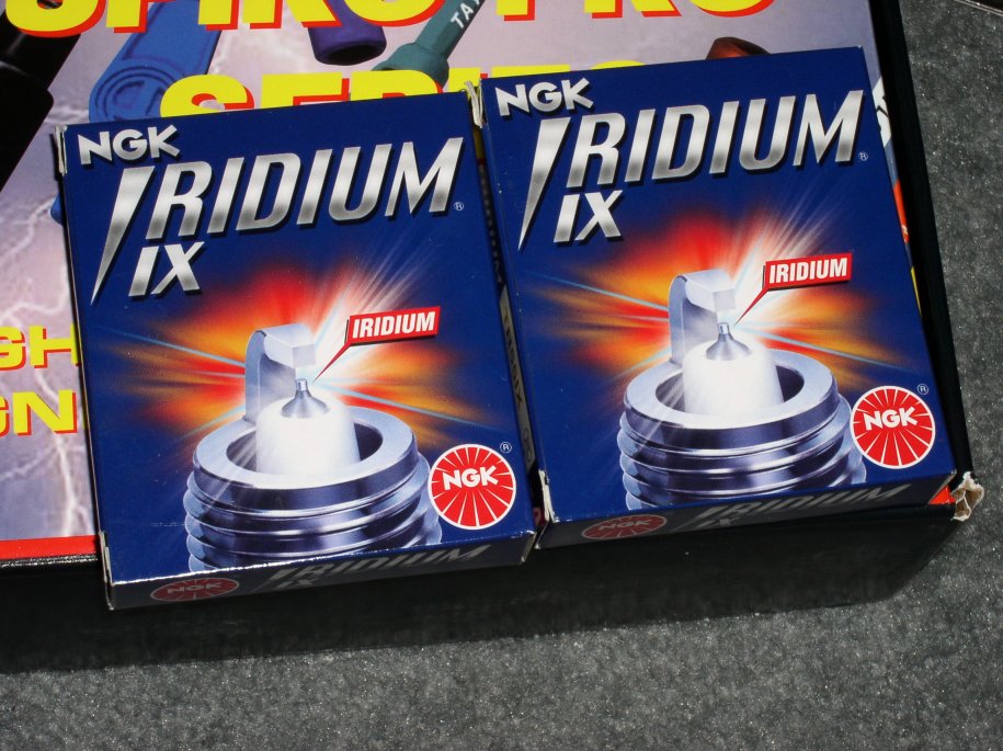
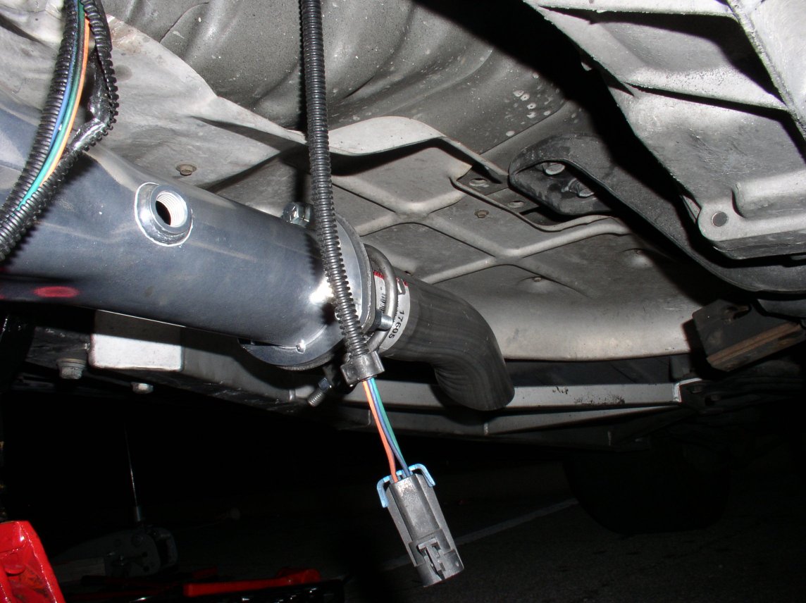
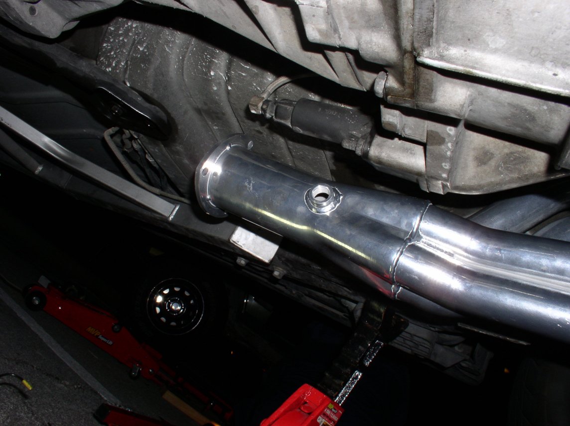
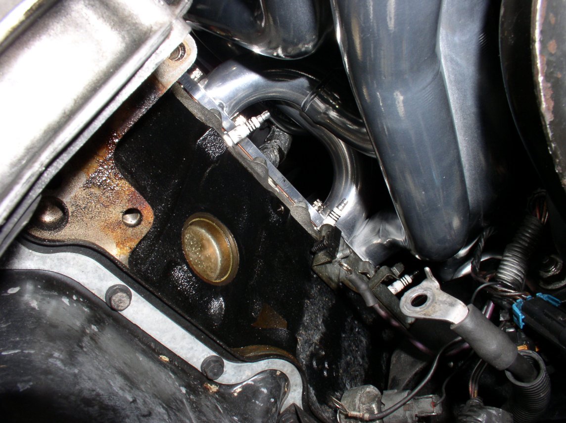
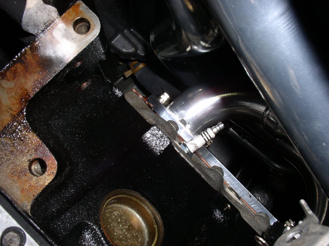
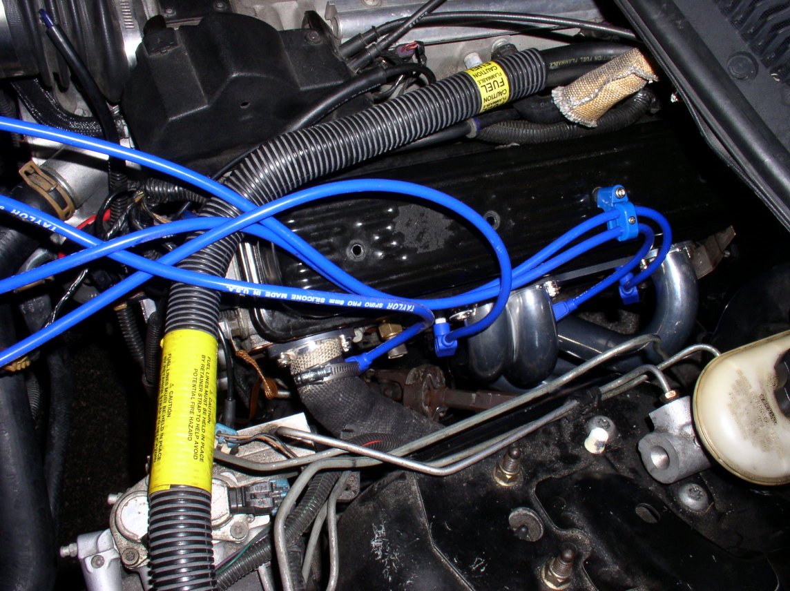
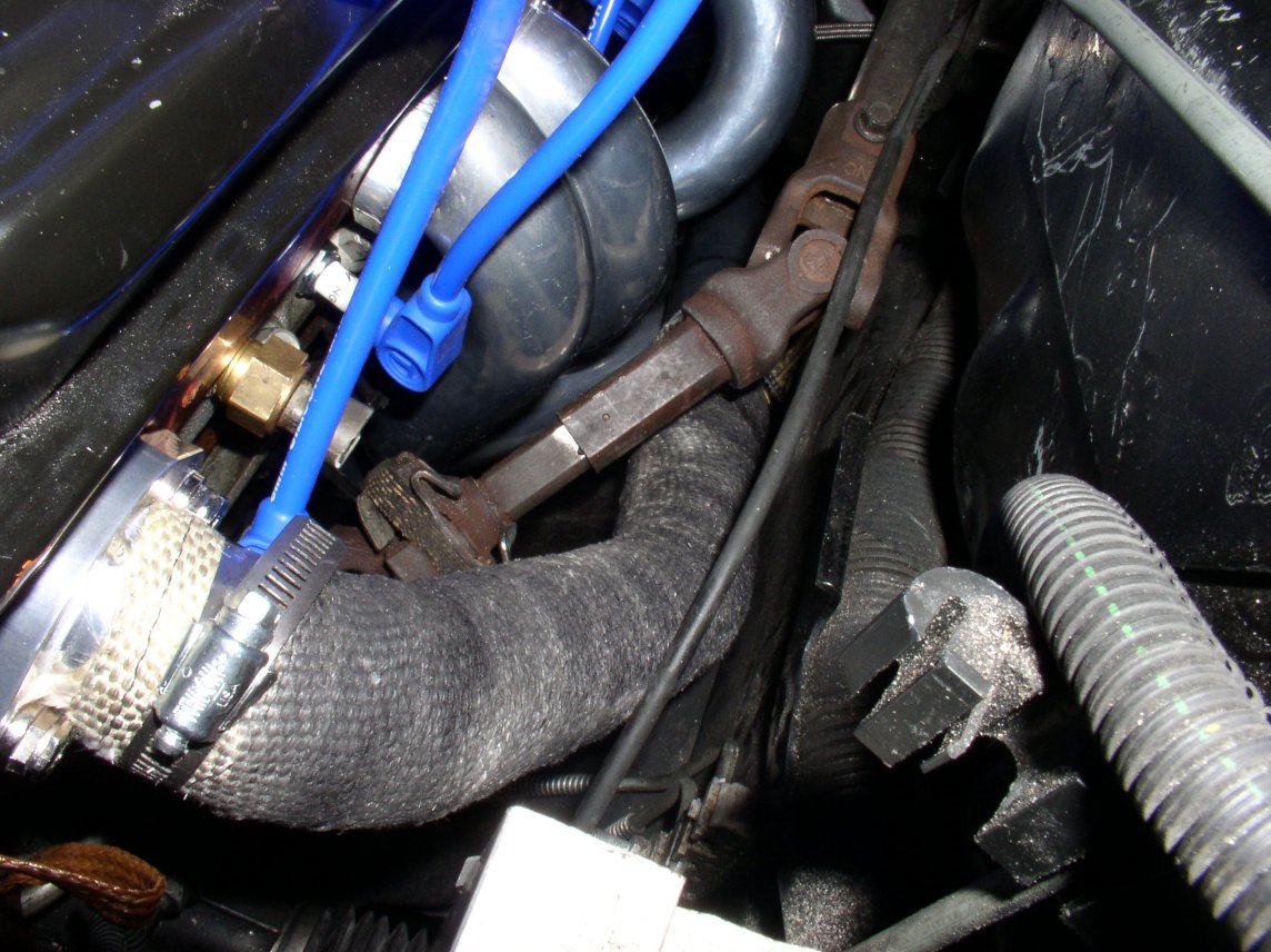
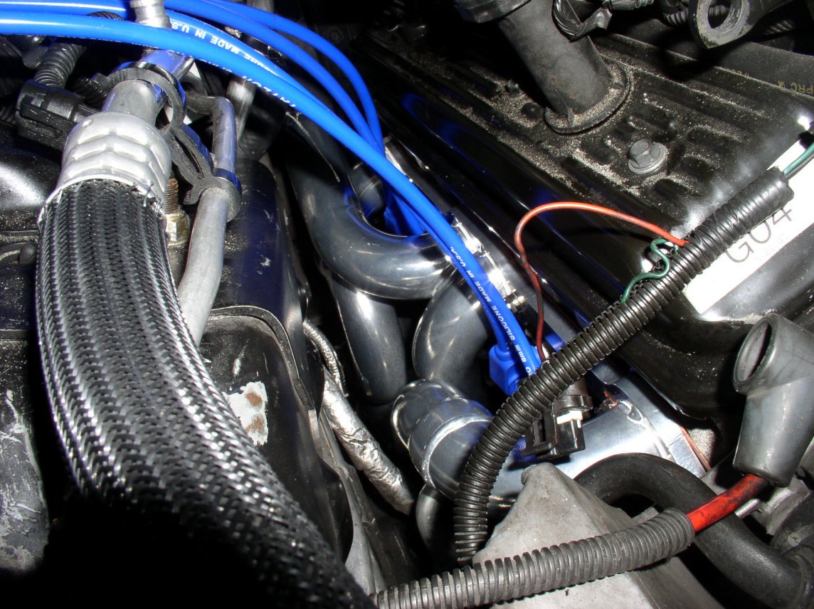
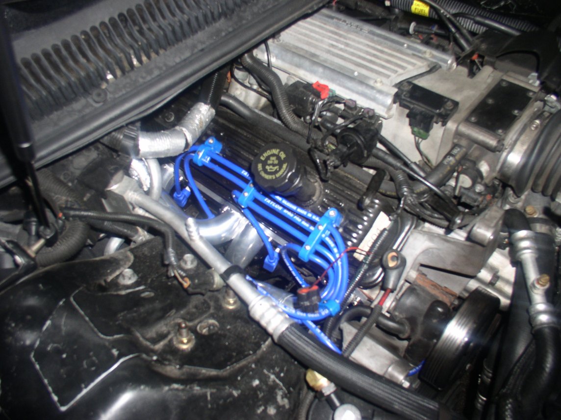
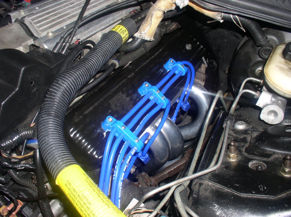
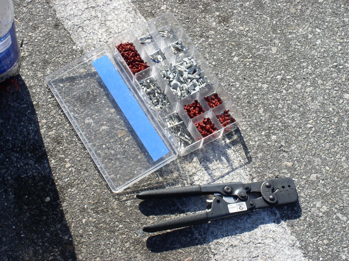
The extras I ordered all arrived first:

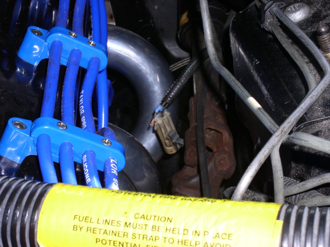
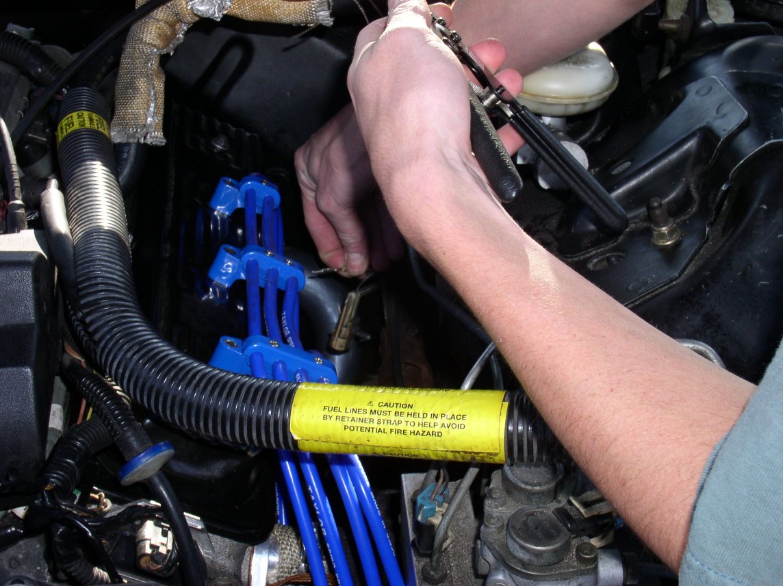
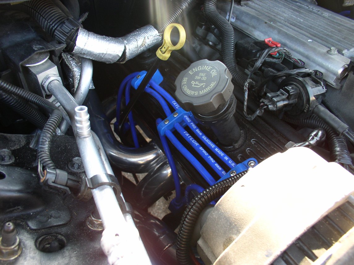
Taylor Cut-to-Fit Over The Valve Cover Wire Kit, NGK Iridium TR55IX Spark Plugs, SCE Copper Gaskets, Oxygen Sensor Extensions, and an OBD1 Conversion with Custom Programming (!AIR, !EGR, !CAGS, 6000rpm rev limiter, no speed limiter, Low fan activation temperatures, slightly desensitized knock sensor, and a corrected fuel enrichment and timing map for a full bolton car) from Ion Soltan (Madwolf). The plug wires are a neccesity with longtubes, and keep the wires tucked away nicely. The copper gaskets will never blow, and the Iridium spark plugs idle better than anything I have ever previously used, and it was a good time to replace them. The OBD1 conversion will give me about 14 extra RWHP on top of the headers, theoretically, and should avoid any SES lights associated with ditching emissions equipment.

The extras: wires, plugs, gaskets, O2 Sensors, PCM with Programming

The actual Jet Hot Headers themselves. The picture does not fully illustrate it, but the insides of the ports and collectors have very clean welds, with no weld slag at all. On the inlets to the primaries at the header flange the port has a very smooth tapered opening. The headers themselves have smooth ceramic sterling Jet Hot coating inside and out and the metal feels very thick and sturdy. The Jet Hot headers feature extra thick collector flanges and header flanges (3/8") over the Hooker design. They also feature improved ground clearance, and O2 sensor bungs welded in the collectors.

The Jet Hot Longtube Headers

Installing the headers

Getting started on the first day. This is the initial height we raised the car up to. We did not find it neccesary to go all that much higher. The goals for the first day were removing the Y pipe, manifolds, and getting at least one if not two headers in. Below you can see the Y pipe being unbolted.

Getting started
Getting started
Getting started
Getting started

The manifold does not slip out all that easily once it is unbolted. All the manifold bolts are 9/16" 6 point bolts. Most of them can be reached from the top with a good ratchet and extension set, and the remainder require box end wrenches, open ended wrenches, or can be done from below. Many of the manifold 'bolts' are also studs, so be prepared. The easiest way to get the manifold out is to have the steering out already. We neglected to do this and therefor jacked up the motor and it slipped right out. We removed the manifolds without fiddling with any of the plugs or wires or coolant sensor. We managed to not break any. Just be careful. They come out the top, not the bottom! Use lots of PB blaster to avoid breakage. Remember to unplug the O2 sensor before you try to extract it. Also, AIR will need to be removed in one way or another before it can be extracted. This is a good time to remove the AIR pump and AIR hard line that runs around the oil pan and timing cover. There is also a vacuum line for AIR and an AIR solenoid on my OBD2 car. We removed the T junction from the intake manifold vacuum ports and bypassed the AIR solenoids altogether.

Removing the exhaust manifold

For preparatory reasons, we removed the oil filter. This absolutely needs to come out for the drivers side header to go in.

Removing the oil filter for clearance

You need to make sure if you had an organic manfold gasket you get the ports very clean. I had a triple-ply stainless steel gasket and had very little cleanup to be done.

Cleaning up the gasket surfaces

A view from below on the passenger and then drivers side respectively. The passenger side manifold remains at this point. We chose to leave the O2 sensors in the manifolds until we had them out of the car. There is much more room this way and they dont really get in the way. The drivers side appears quite roomy with these things removed, but it is definitely an illusion.

Drivers side manifold removed

The crew regrouping in the fading light and dropping temperatures. We had the passenger side manifold out in no time after we remembered to disconnect the EGR pipe from the intake manifold first. We also took the opportunity to unbolt the bracket on the dipstick tube and remove it.

Fading light

Next we decided it would be best to try the passenger side. This will give you an idea of how hard your entire install will be. If the passenger side is hard, don't fret, once it is in, you are out of the woods. If the passenger side just pops right in, be afraid, be very afraid. This means the drivers side will be a bear. To insert the passenger side header we removed the starter, and unbolted the motor mount on the passenger side. With a jack positioned as shown, and the SHIFTER IN NEUTRAL in the passenger compartment (to prevent transmission damage) we lifted the motor all the way to the cowl. This is easier than it sounds. The tools shown below will accomplish the job of unbolting the motor mounts. Support the motor as shown, and barely make contact. Begin loosening the motor mount bolt and nut. You need a 15mm for the bolt and a 18mm deep well for the nut. Once the nut is off, the bolt can be extracted. If it is not loose in any way, you will need to play with lowering and raising the jack just a little bit so as to support the motor correctly. You will know once it is correct since the bolt will slide right out. Once this happens, jack the motor up as high as you need. Stop once the motor doesn't appear to be raising any further. Have someone spot you.

Installing the passenger side headers

In this configuration, the header literally can be thrown up into the engine bay. Have someone ready, probably on a stool or chair, to hold it up and install one or more bolts, as needed to support the header. Lower the motor all the way back down, and let it rest on the mounts. Then, take a look at the motor mounts. You will be able to see when it is close to lining up. Bring the motor up slowly, while trying to reinsert the bolt. Remember, bolt to the front of the chassis, nut to the rear. Once it is lined up, it should slide right in as before. Tighten these down very tightly, but not excessively. As you can see, the passenger side header has plenty of room.

Passenger side header room

This is the pile of parts. You can see the chair we used as a stool, along with countless other car parts and tools.

The pile of parts

This is the drivers side all cleaned up and ready to accept (or so we had hoped) the drivers side header. We jacked this side of the motor up as we had done the passenger side, removed the steering linkage (two 11mm bolts), all the plugs and wires, and held our breath...

Preparing the drivers side

...But we were to have no such luck. The header stood no chance at all of going in, even with the motor jacked to the cowl, oil filter and steering removed, and everything out of the way. We even raised the car futher, to an astonishing 24" to the K member, and no way, no how was it going in. It would just barely not clear the K member lip.

K-Member interference with drivers side header

More help began to arrive, but to no avail. The parking lot did appear to be an F-Body meet though.

Help arrives

The smaller the block of wood or 'substitute wood' you can find to jack up the motor with the better off you will be. Unfortunately for us, though, it still wasn't happening. Here you can see the header not clearing the low oil sensor when installed at another angle. We decided it would be fruitless to remove yet another sensor until we took stock in our position again.

Header clearance issues continue

Day two begins. We decide that we are going to have to notch the K member, and if we get stuck completely, even drop it. Our attempts to notch the K-member were not successful. They helped in a small way, but ultimately they would not allow us the geometry we needed. We entertained an idea presented by our friend Brett from MASC Performance (www.mascperformance.com, pictured below) to try to pry down one side of the K member.

Trying to notch the K-member

The determination was made, the K member had to come down. The K member or cradle has 3 bolts on each side. Each of them is easily reached, though one of them must be gotten with an extension through the holes in the A arm. These bolts need to be totally removed. Do not be overly concerned with being able to line these up again, as the mounting brackets slide around for adjustment. Unbolt and remove all 3 drivers side cradle bolts with the motor supported by the oil pan. Loosen the 3 passenger side cradle bolts a tad. Jack the drivers side back up, leaving the passenger side motor mount connected. Then, fit a pry bar between the cradle and the body as shown and apply a little gentle persuasion. This provided us with just the leverage we needed to get the header in.

Lowering the K-member

The header is in! You can see at left the damage we did to the K member when we notched it for hours with a hacksaw. Luckily we just trimmed the lip a bit, and nothing structural. To the right you can see the removed valve cover, which we thought might allow us to install it from the top, but this turned out to be a short lived ill-fated attempt. It will NOT go in from the top.

Drivers side header is in

A decent view of both headers from the front.

Header collectors from the front

The #1 primary tube on the Jet Hot longtube headers rubbed on the hard brake line on my friend Adams car resulting in a burst brake line and lots of damage. To avoid this, I removed the metal heat shield altogether. Then, I relocated the hard brake line by gently bending it up and out of the way as pictured. This is a neccesary modification for my car, but your mileage may vary.

Moving the brake hard line to avoid header interference

Hooker Y Pipes were backordered everywhere, so I chose to use a set of Autozone header collectors and turndowns.

Improvising a solution due to lack of Y-pipe

There is an upside down U shaped HARD A/C line eminating from the back of the compressor on the passenger side. Make absolutely sure it is not touching the #2 header primary. I had to use a pry bar on mine to clearance it.

Clearancing A/C lines from the headers

A good view from up top with the majority of the header bolted up and the copper gaskets prepped with RTV awaiting the slip fit primary tube.

Drivers side header from above

This was THE tool to use for the Stage 8 header bolts. It is a 1/4" drive ratchet with a 1/4" socket. Inside this socket is a drill chuck drive 3/16" allen key. This exactly fits in the heads of the Stage 8 bolts and makes the job monumentally easier.

Stage 8 header bolts tool

A few random views of the headers, collectors, and etc.

A few random views of the headers, collectors, and etc.

A few shots showing the access you have to tightening the passenger side rear 3 header bolts and spark plugs. This job is easy with a good semi-short 7/16" open ended wrench. Box ends will not clear the primaries.

A few shots showing the access you have to tightening the passenger side rear 3 header bolts and spark plugs

The headers are bolted up in place. A shot of the header collectors and the ground clearance. The Jet Hot longtubes barely protrude below the SLP Subframe connectors I have. They cleared the killer speed bumps in my apartment complex also.

The header collectors and the ground clearance

The beginnings of the Taylor OTVC wires. You can see the #1 slip fit primary tube we installed with header wrap and silicon spray. Also, we reinstalled the steering, and moved a few other things out of the way, namely the cruise control cable. To bolt the #1 primary on once it is slipped in, you will need to hold it away from the head mating surface slightly so you can fit the length of the 1" long Stage 8 7/16" bolt through and get it threaded. This allows you a straight shot at the head bolt hole. You do NOT want to crossthread these. The steering knuckle also had two small tabs on the rounded 'cardboard' portion near the bottom. We pounded these down to clear the header. They would catch when the wheel was turned.

The beginnings of the Taylor OTVC wires

The transmission crossmember brace had to be trimmed.

The transmission crossmember brace had to be trimmed

The completed and routed Taylor OTVC Wire kit. This really keeps the wires away from heat sources. I have no concerns at all with burning these. The crimp to length connectors are a hell of a task though. The only humanly possible way we found to get the Optispark ends on was to take a flathead screwdriver, cram it all the way through while twisting to stretch the rubber, then lube it up with WD40 on both the wire and the boot and just push it through and pray. It is very trying but it works out. Also, make doubly sure to crimp the Opti terminals on the wires TIGHTLY as they can come off when pulled on.

The completed and routed Taylor OTVC Wire kit

The ABS sensor harness on the drivers side body is actually a little close to the slip fit where it clips stock. We pried out the clip and moved it. When separating the weatherpack connector, we noticed the harness end was damaged. We called our friend Ryan "Slow" from our car club to come over. He sells fan switches and other harnesses that he makes with weatherpacks so he brought his weatherpack toolset. He was able to replace the broken part of my weatherpack connector on the body harness side where the wire had pulled out in no time. His help was invaluable.

Moving the ABS sensor harness

The alternator and dipstick tube are back in. The dipstick tube required a little trimming at the end, and sanding down. This makes it easier to reinsert and line up the bracket to bolt back to the block.

The alternator and dipstick tube are back in

This is my EGR blockoff plate. We took the stock EGR flex pipe from the passenger side manifold and cut out the tube and then cut a coke can to shape and RTV'd it to the plate and bolted it down. Works beautifully.

EGR blockoff plate

The final pictures of the completed engine bay. Looks much nicer than before.

The completed engine bay

The final ground clearance, after the car settled back down on the ground. Not bad at all. I lost less than a centimeter on either side compared to my previous setup.

The final ground clearance

Hooker Y Pipe Installation

Here is the Jet Hot coated Hooker Y Pipe. You can see it's clearanced on the drivers side for the transmission crossmember. It is coated inside and out and has excellent finish. It alsois supposed to maintain excellent ground clearance.

Jet Hot coated Hooker Y Pipe

The Y pipe is finally bolted up. It should be fairly self-explanatory. The header flanges were a very hairy situation, but we got them bolted down flush and flat. The Y pipe was too wide at first, and we realized the drivers side portion would need tohave approximately 1/4" removed from the slip fit area to bringthe rest of the pipe forward and inward. Once we did this thepipe could finally be fitted up.

The Y pipe is finally bolted up

The clearance against the crossmember is very tight. The pipe touches the floorboard sometimes when the motor torques, but it should be ok since it is coated and the body of the caris a significant heat sink. The only other area of concern isthe fuel and brake lines running near the pipe. I will find something suitable to shield these. Header wrap ought to be sufficient, since it has worked well in the engine bay where temps are muchhotter.

The clearance against the crossmember is very tight

You can get an idea of the ground clearance from these shots. This Y pipe barely comes below my boxed subframe connectors, meaning that if i were to scrape it (and I haven't yet) the subframes would absorb most of the impact, which is what I want.

Ground Clearance
Ground Clearance
Ground Clearance
Ground Clearance
Ground Clearance

Results

A Little Subjective: I love these headers. They sound great through the Corsa, and they have been absolutely painless to live with. So far Ihave not even one leak, not even one burnt wire or sensor. Thefeeling of all that extra torque is amazing at lower RPMs. Theseare the best HP mod I have done so far. The track results speakfor themselves...

Before: 14.1 @ 99.2 - 2.1 60' After: 13.4 @ 104.5 - 2.2 60'

That is a gain of 7 Tenths and over 5 MPH... and there is more in it with that 60'!


The Gang

Some shots of the first day crew including Makoto.

Some shots of the first day crew including Makoto

Four of the F-Bodies that just stopped by to help as they passed by.

Four of the F-Bodies that just stopped by to help as they passed by

Left to right, Adam (LeftoverChinese), Brett from MASC Performance, and "Redneck" Joe. The "Dip Clip"

Left to right, Adam (LeftoverChinese), Brett from MASC Performance, and "Redneck" Joe. The "Dip Clip"

Joes 2000 T/A WS6

Joes 2000 T/A WS6
Joes 2000 T/A WS6

Jeff's (Borsos) Jeep with a 4.5" lift and 31" Tires. On the right, Jeff finding a new use for a gear wrench.

Jeff's (Borsos) Jeep with a 4.5" lift and 31" Tires. On the right, Jeff finding a new use for a gear wrench.