Big Brake Kit Install
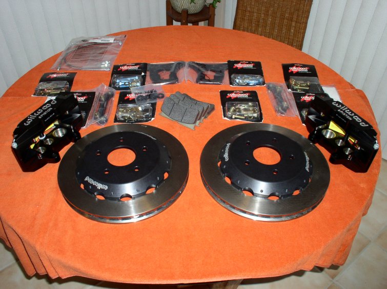
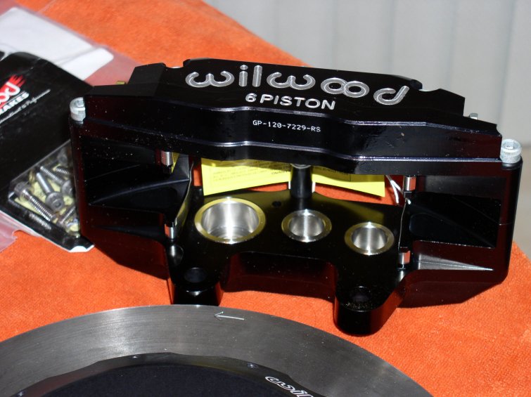
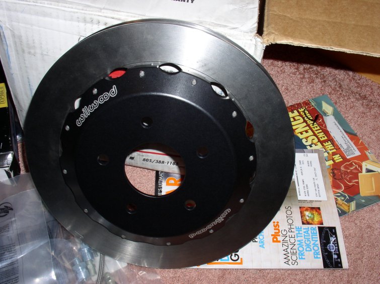
The Kit as it arrived...
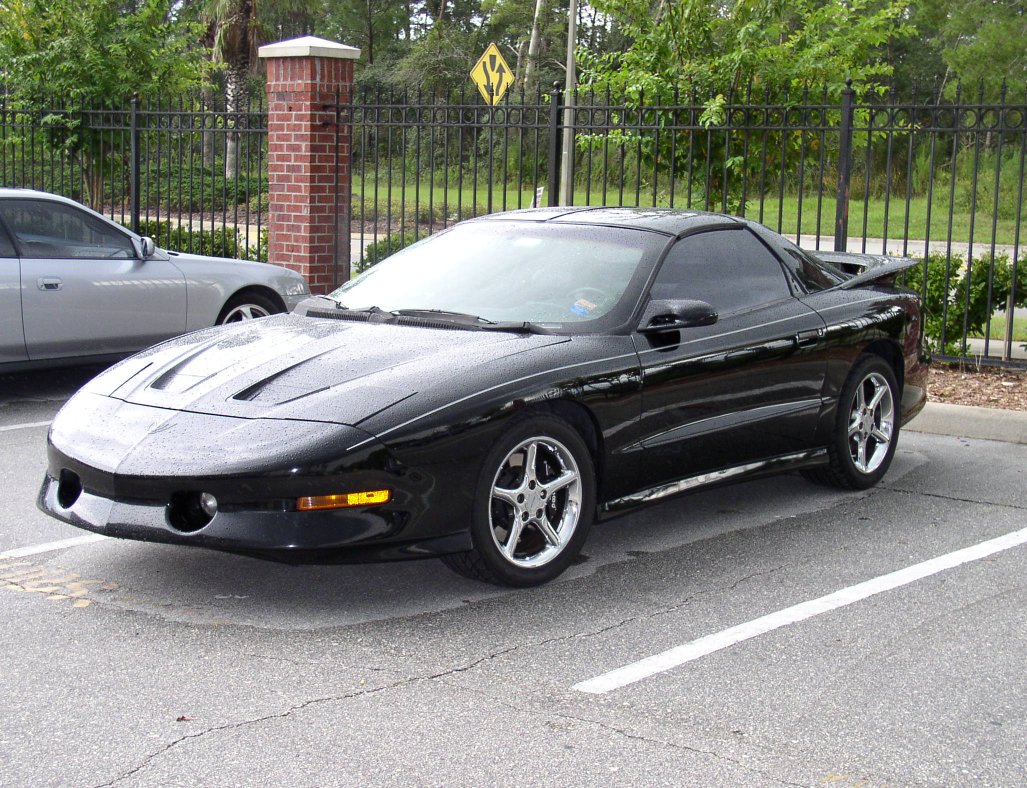
1997 Pontiac Trans Am Project Photos and Installation Guides

The Kit as it arrived...
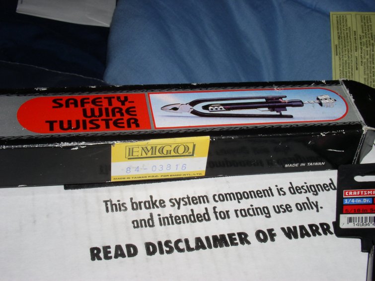
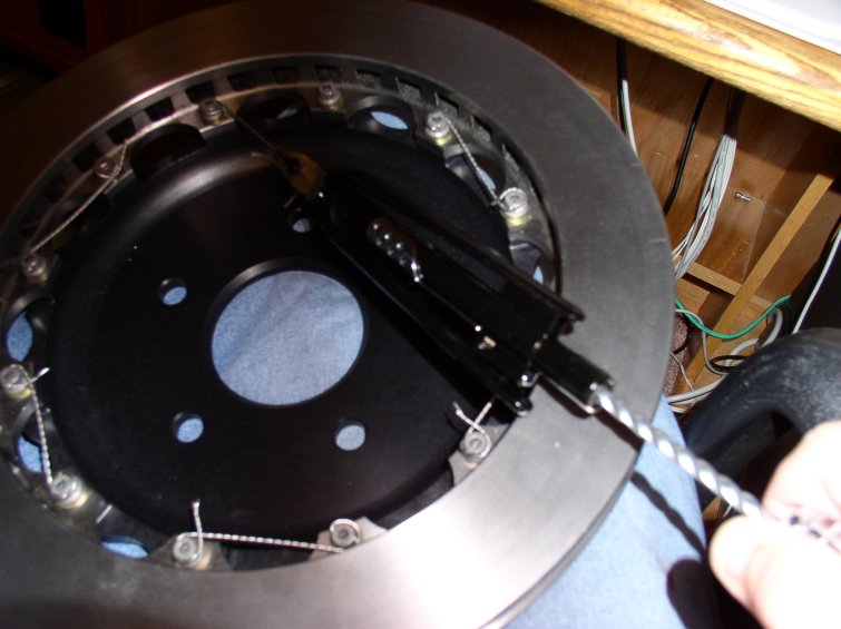
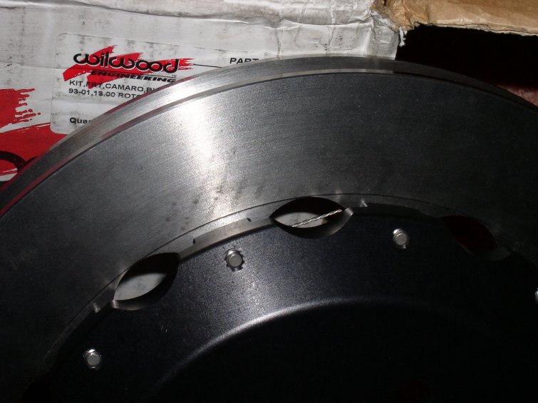
First step to install, bolting the aluminum hats to the rotors.The aluminum hat is bolted to the rotor via twelve (12) 5/16" 12 point bolts and washers. The bolt heads are drilled on two axis to allow the use of lockwire or safety wire. Getting ready to begin, here you can see the safety wire pliers and wire loom:
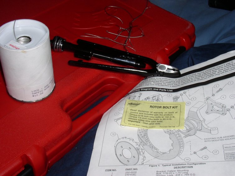
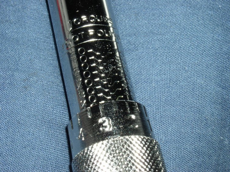
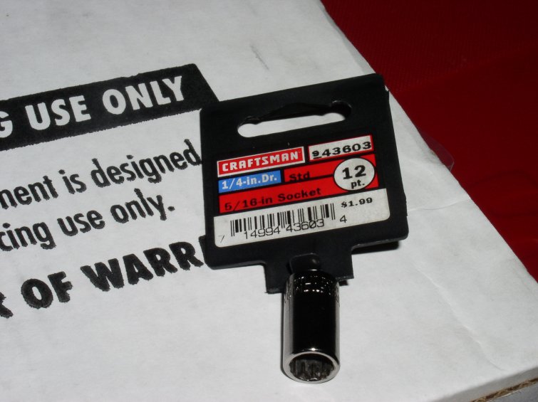
The 5/16" 12 point bolts are specified at 85 in/lbs torque in the install document, but the rotor bolt kit specifies to use 150 in/lbs. I decided to follow the bolt kit instructions. 150 in/lbs is roughly 12.5 ft/lbs, so good luck finding a torque wrench that can measure low enough. I also had to go buy a special 1/4 inch drive 12 pt. socket. Oddly enough, I ended up two bolts short. Wilwood promised me they would mail me a pair.
The basic safety wiring process:
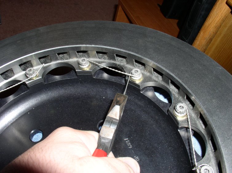
Start with a 8 or 9 inch length of wire, and thread it through two holes in the bolt head.
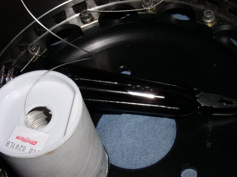
Wrap the wire around the bolt head in a clockwise direction, tighten any slack, and grip about a centimeter past the second bolt head, and twist three or so pulls with the pliers. Thread the remaining tail around the second bolt head counterclockwise with one wire running through the bolt head itself. Pull tight, and twist with the safety wire pliers two to three turns, being careful not to lose the tension.
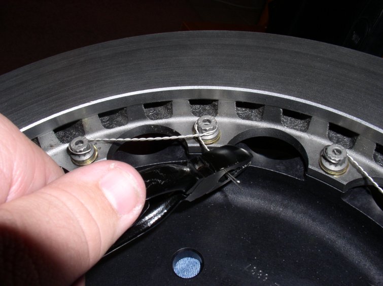
Clip the tail end at around half an inch length. The final result should look something like this.
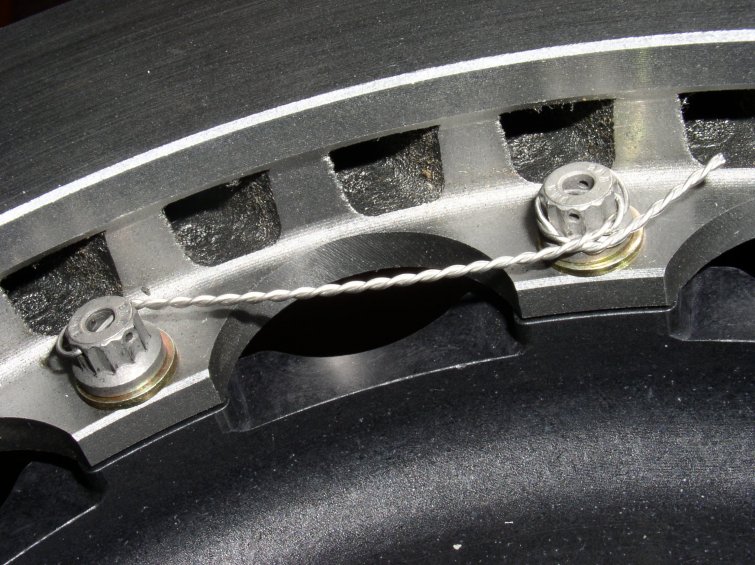
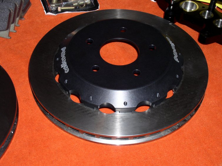
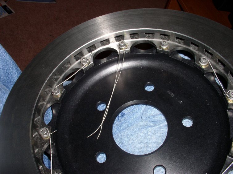
The rotor, with the safety wiring complete.
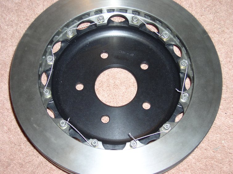
The completed assembly. Notice you can see the safety wire in the second pic.
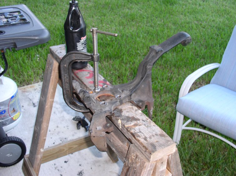
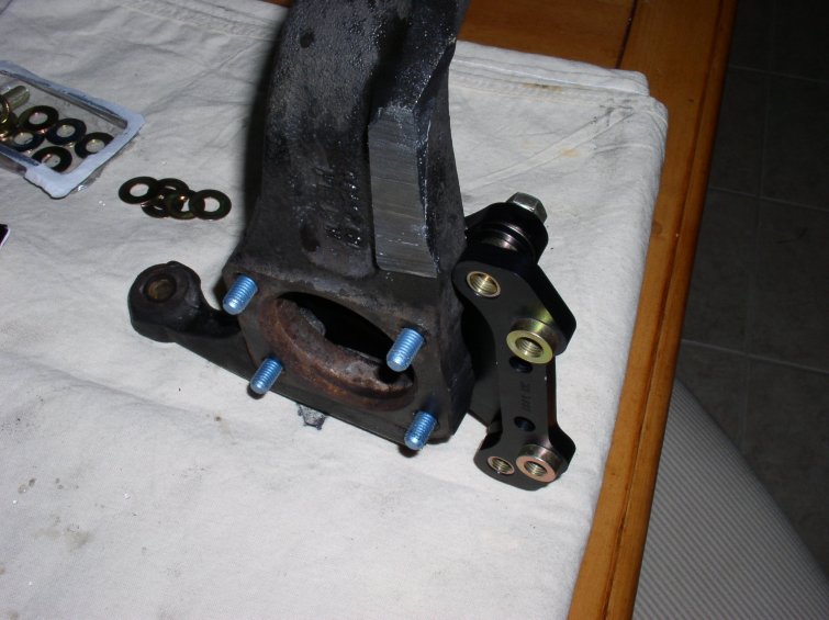
In order to mount the caliper and mounting brackets, the factory spindles need to be modified:
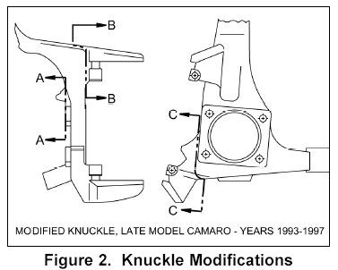
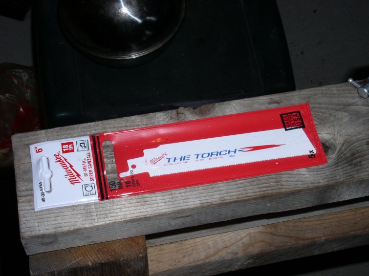
The following are some pictures of the spindle modifications required to mount the caliper to the steering knuckle. We did these cuts with a Sawz-all OFF OF THE CAR. You can follow instructions, but its just as easy to see what needs to be cut when you're looking at the brackets. Use a heavy duty sawz-all (I rented one) and buy some oil and plenty of blades. I used Coastal 75W90 Gear Oil, and Milwaukee 'Torch' metal cutting blades. I bought a pack of 5, we used 4. Also have handy some c-clamps and other creative ways to keep this thing still.
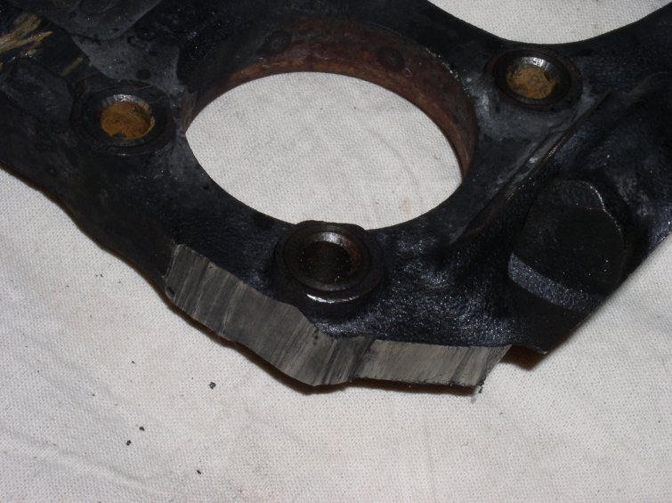
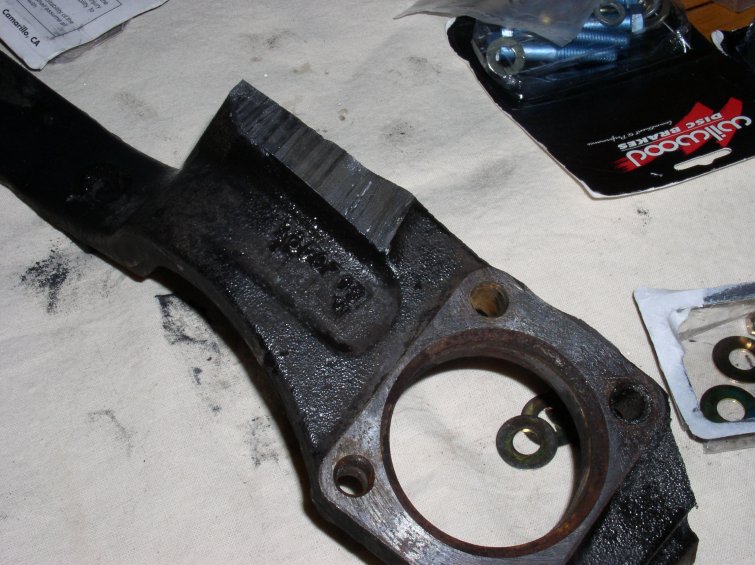
Below you can see why the cuts are neccesary, as they remove the stock mounting 'ears' which interfere with the Wilwood brackets. We test fitted these, which was a good idea, since unless the alignment is perfect (and there is some play to it) the hubs will not let the bolts thread in. We torqued these to factory specs (63 ft/lbs) since we could find no other spec, though the Wilwood bolts are much more substantial.
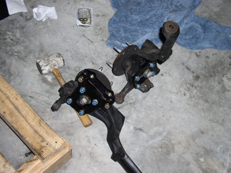
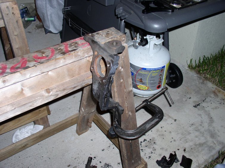
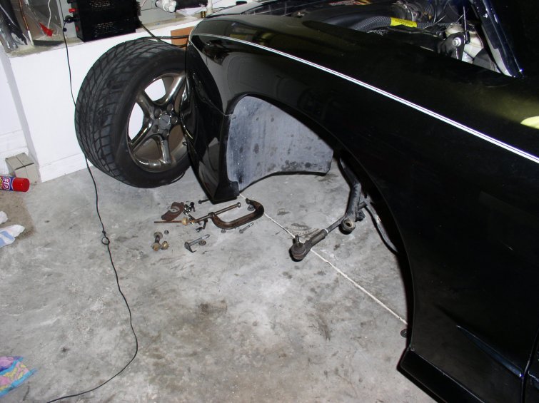
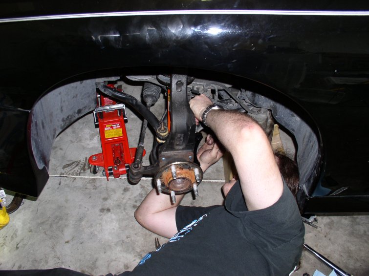
Here is the process for removing the front suspension and steering knuckle. If you do not have spares for modifying, like I did, you would then have to modify these. It is possible to do it on the car, but I would not reccomend it due to the mess.
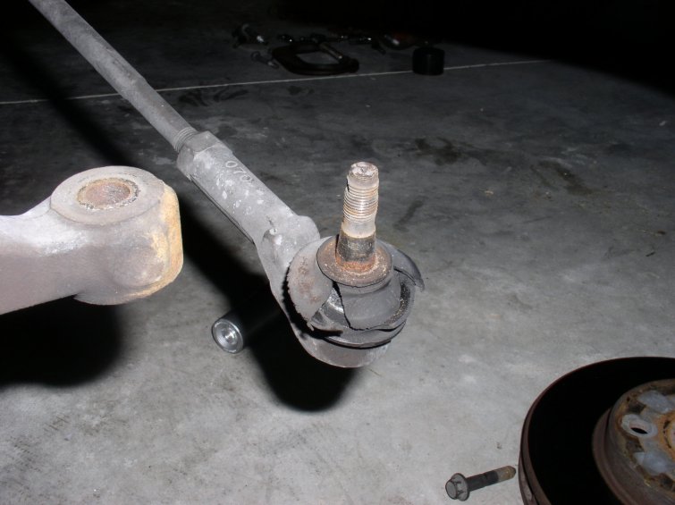
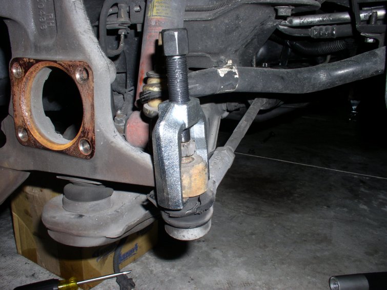
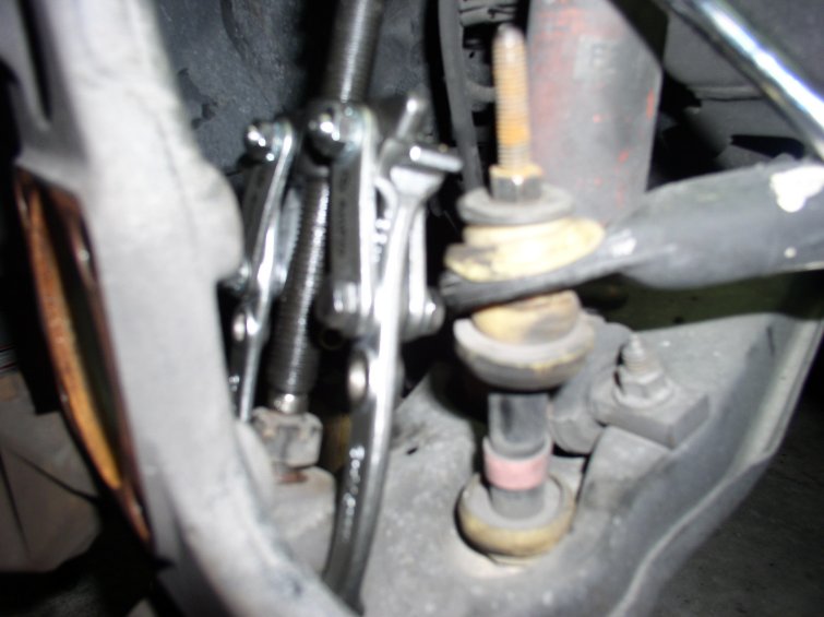
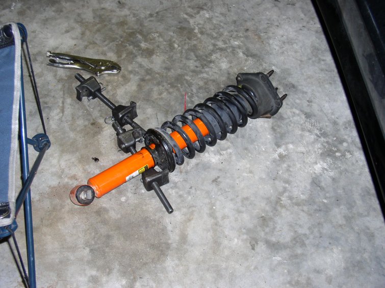
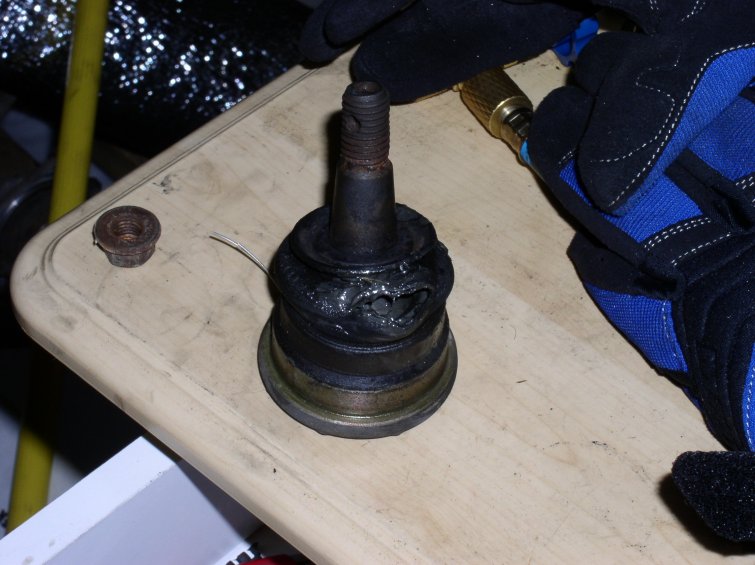
I took this (great) opportunity to replace my stock front shocks also. A word to the wise: do NOT under any circumstances use a pickle fork to separate the balljoints. Use a pitman type puller or a gear puller. I ruined one lower ball joint this way. (Removing the A Arm is a lot of work if you get yourself into this situation) The puller on the left is a Pitman type puller. On the right is a 2 jaw gear puller. Both work great. Remove the cotter pins, loosen (but do not remove) the castle nuts, and pull the ball joints. (This is very loud. And I cannot stress how important it is to leave the castle nuts slightly on, so the parts do not go flying. Once this is complete, remove the castle nut) Once all three are out including the tie rod end (good time to replace this) you should be able to remove the steering knuckle. This is why you might want to replace a tie rod end:
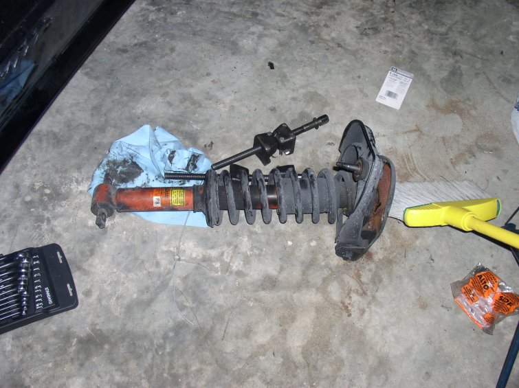
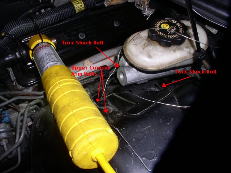
The stock shock mounting assembly removed from the upper A-Arm. To the right, the master cylinder is removed from its locating studs. A note about shocks:
If you decide to do this, you need a heavy duty spring compressor, and a torx bit (don't remember the size). To do the drivers side, it will be neccesary to remove the master cylinder from its studs and set it aside slightly. Mine were frozen on beyond belief. This is easier said than done. Remove the upper and lower shock bolts, and it falls right out. Then you compress the spring and swap the old spring to the new shock.
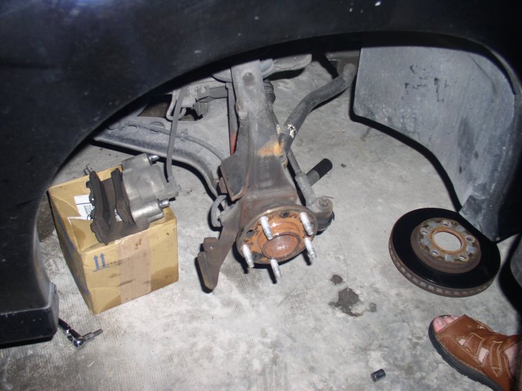
This is the stock passenger side knuckle and hub assembly. To remove the hub, disconnect the ABS sensor, and remove the four 13mm bolts. Its very self explanatory once you are looking at it. Pound out with a rubber mallet.
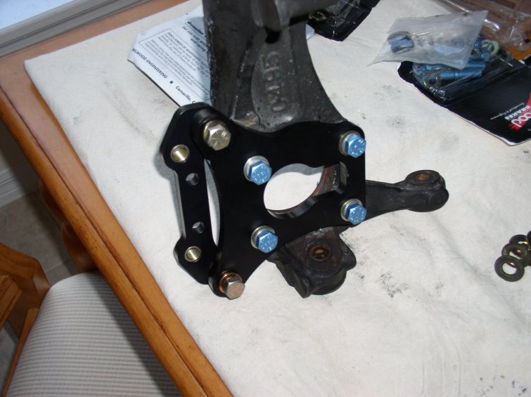
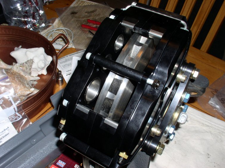
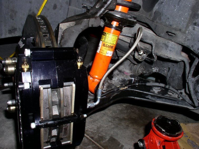
At this point, we decided to mock up the brakes completely to the spindles to check for fitment, alignment, and any other problems we might have encountered. It lined up perfectly on the first shot, and we did not have to shim it. The bracket for the caliper bolts to the caliper first, however, and then AFTER the rotor is placed on the hub, the caliper can be slipped over and bolted on using the bracket and bolts from behind. You will not be able to remove the caliper to caliper bracket bolts once the caliper is on the rotor. Do not make the misake we made, and have to do it again.
Note about these pictures: You do not want to install the brakes as you see in the first two pictures. The bracket with the brass fittings actually gets bolted to the caliper first, and then the whole caliper/bracket assembly gets bolted to the bracket you see below. This is so you can fit a wrench on it once the rotor is on the hub.
These are mocked up completely as they would be placed on the car. I would reccomend that you do this, since it is easier to see these things when you are not inside the wheel well. Notice the safety wiring of the bolts on the rotor from this view. You want to make sure you apply red loctite to most of these mounting bolts, specifically the caliper bracket.
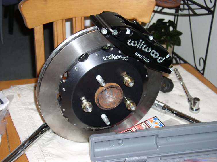
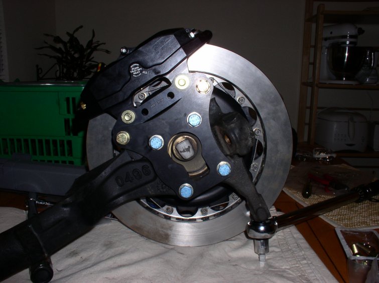
The important thing here is that the rotor is equally spaced from both sides of the caliper, and perfectly centered. As I said, mine lined up without any adjustment.
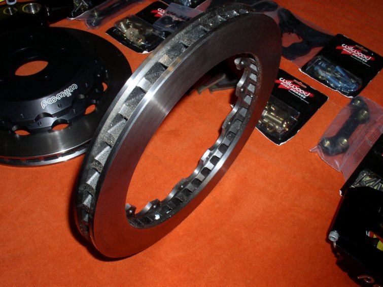
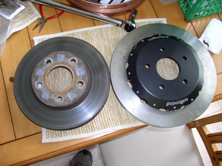
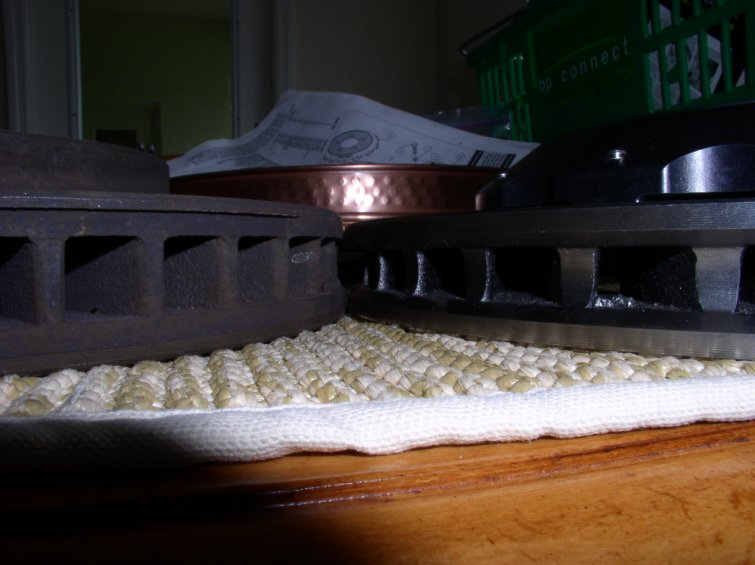
Here is a quick dimensional comparison between stock and Wilwood. The stock rotor is smaller in diameter, but larger in thickness. It is also a full 2 lbs. heavier per rotor than the Wilwoods, which is amazing, given the increase in overall size.
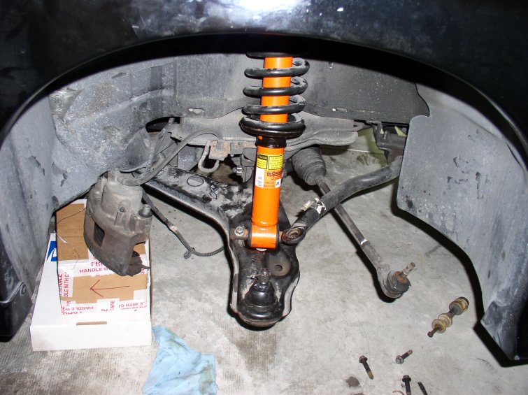
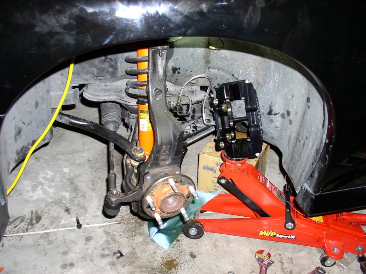
Here is the passenger side A arm and coil over shock assembly. Swapping these springs is a chore with a manual spring compressor. We swapped one then paid a shop to swap the other. You can see the ball joint located in the lower A arm. As previously mentioned, mine were ripped, so it was an obvious decision, but you would be advised to replace your stock ones. Removing the A arms is easy, remove the sway bar, and two huge nuts (the position of these dictates your alignment! Mark their location and you MUST get an alignment immediately) which are removed easily by wiggling the A arm itself or by moving the steering wheel left or right to get the neccesary clearance. You are going to want to make sure that facing the shock, the two lower feet that slope away from you (since the A arm droops) are perpindicular to the two studs on the upper shock mount. You will never get it aligned and bolted up otherwise, and you must compress the spring to rotate it.
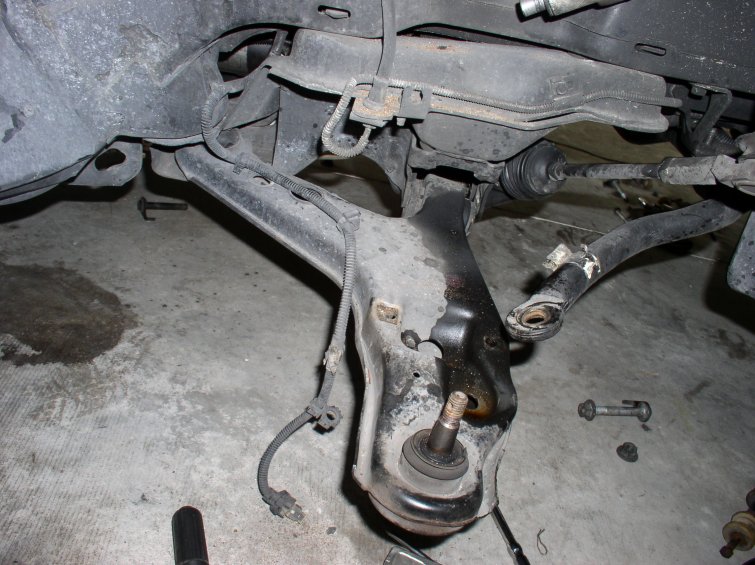
Here you can see the ruined lower ball joint, and the front suspension totally removed. Tire Kingdom charged me 1.5 hrs of mechanical labor to press out the old ball joint on one side (I had previously removed another, DO NOT attempt this, they are extremely tight and they exit at a high velocity when popped out) and have two new ball joints pressed in, along with swapping springs.
New shock and spring are installed, and shortly afterward, the spindle and hub. The spindle goes back in extremely easily. The ball joints are pressed back together by the torque spec on the castle nut on top of it. The lower ball joint, for instance, you thread in the castle nut, and then start torquing it down to 85 ft/lbs. At 85 ft/lbs, try to fit in a cotter pin, and if neccesary torque more (barely) till it goes in the hole evenly. Twist the cotter pin like it was stock to retain the castle nut. The upper ball joint requires you place a jack under the A arm and lift it up, while pulling down the upper A arm. It is easier than it sounds. Do not forget to reattach the tie rod ends. I chose to replace mine, but you can not remove the jam nut without the castle nut going through the spindle since it twists everywhere. The jam nut goes the opposite way you would expect. Loosen it by rotating it in such a way that it moves up on the tie rod towards the steering rack itself. Then the tie rod end comes off easily.
At the last moment possible, remove the stock brake line fitting. This is really difficult until you figure out how to do it. Pry the clip off with a screwdriver, and then place a 12mm flare nut wrench on the bottom wrench flat (hard line) and a 5/8" open ended wrench on the top wrench flat (soft line). After that it is a simple matter. Making sure the fluid level in the resovoir does not drop (it will come out due to gravity, through the opened lines) quickly connect the replacement brake lines, and then those go into the caliper. A note about the Wilwood brake lines. They give you two silverish line fittings. You don't need these. You use the brass fittings only, and the FLAT end goes into the caliper, and the pointed end goes into the line. They are the same thread pitch, so do not make this mistake. You will leak brake fluid everywhere.
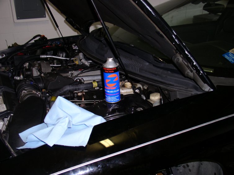
On the left, our brake fluid of choice waiting to go in as we are bleeding the brakes. Performance Friction Z Rated DOT 3 High Temp brake fluid, you can get this at any Autozone, but it is behind the counter. On the right, the brake line attached, and the brakes fully assembled.
You can see the tightness of the rotor and the pads here. There is no empty space at all. Do not be concerned if you seem to have a slight runout (drag) on the rotor. This resolves itself within a few feet of driving. Do not forget to tigten the bridge bolt when you put in the pads. Now bleed the brakes. Starting with the new calipers, decide whether or not to bleed these immediately. Ours were mostly 'gravity' bled, since we had the bleed valves open while hooking up the lines, and fluid was literally pouring out, so we knew they had fluid in them. Start farthest from the master cylinder (passenger rear) and then the next farthest (driver rear). We used a one man bleeder system which makes this process much easier.
DO NOT LET THE MASTER CYLINDER RUN DRY.
Next, go to the front right caliper, and bleed the outside bleeder valve first, then the inside. Repeat this way for the left front. You should have a rock solid pedal by now. You're done! Check all the bolts and don't forget anything. Bolt up the wheels and go test the brakes gently. Do not be surprised if your alignment is off by a lot. Get an alignment immediately, then bed the pads and rotors following Wilwoods instructions. Have fun!
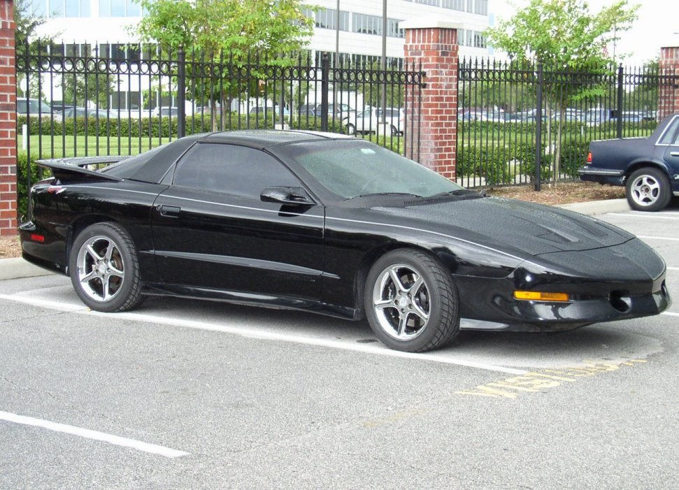
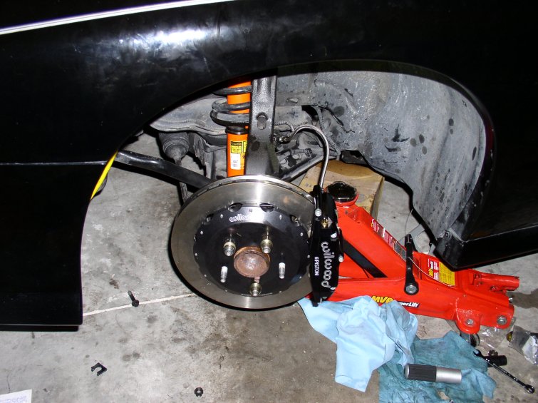
The finished product. This is what its all about right here:
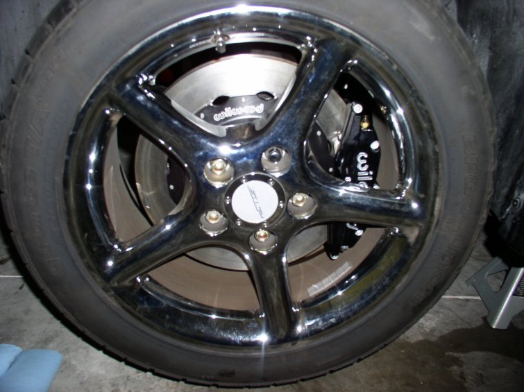
And the subjective:
Words cannot describe the difference these made. My alignment is so far off (the wheel is 90 degrees or more off center from the steering) that I have not even yet ventured to standing on the brake pedal, but even at light pedal effort, these brakes will have you kissing the steering wheel. I noticed a difference from every speed above 30mph or so. Simply incredible how little pedal effort it takes now to bring the car to a screeching halt, and like I said, I havent even gone all out yet.